Recliner regulating device

a regulating device and reclining technology, applied in the field of mechanical technology, can solve the problems of weighing and bulky device structure, increased device thickness, poor manufacturability, etc., and achieves the balance of stress on locking cam and unlocking cam, and the effect of improving production efficiency

Active Publication Date: 2010-11-02
HUBEI AVIATION PRECISION MASCH TECH CO LTD
View PDF9 Cites 0 Cited by
  • Summary
  • Abstract
  • Description
  • Claims
  • Application Information

AI Technical Summary

Benefits of technology

[0016]Several advantages of the device according to the invention described include the thickness of the locking cam and the unlocking cam which may be determined separately depending on their subjected stress. It is optimal when the thickness of the unlocking cam is less than that of the locking cam and when the thickness of the locking cam is identical with that of the sliders. In this case, stress on the locking cam and the unlocking cam is balanced most. Meanwhile, since the locking cam and the unlocking cam are manufactured separately and satisfy the punching condition, the production efficiency is significantly improved compared with that of the integral cam.
[0017]When adopting three sliding grooves and three sliders, the device enables both the self-centering of the central shaft and the angle locking-up of the recliner, so that engagement between the slider teeth and the ratchet gear teeth are more stable.
[0018]Moreover, jacket-type configuration is adopted in the device, which makes its entire structure simple, installation flexible and also makes the device free of maintenance. Quick-folding of the recliner may be realized at the same time of angle-regulating of the recliner.

Problems solved by technology

As the intensity of the unlocking part is bigger than that of the locking part, when the entire thickness of the cam meets the locking requirements, intensity margin of the unlocking part is oversized, which leads to an increase of the entire thickness of the device and a bad manufacturability when punching the cam grooves 202 and the central hole.
Moreover, it is difficult to manufacture the cam, because the cam has reinforcement ribs and the profile thereof includes a plurality of curved segments.
This device adopts an attaching-type configuration, which leads to the structure of the device ponderous and bulky.

Method used


Image

  • Recliner regulating device
  • Recliner regulating device
  • Recliner regulating device

Examples


Embodiment Construction

[0027]The configuration of the device and the connection relationships among various components of the device are described in detail by way of an embodiment of the invention with reference to the attached drawings.

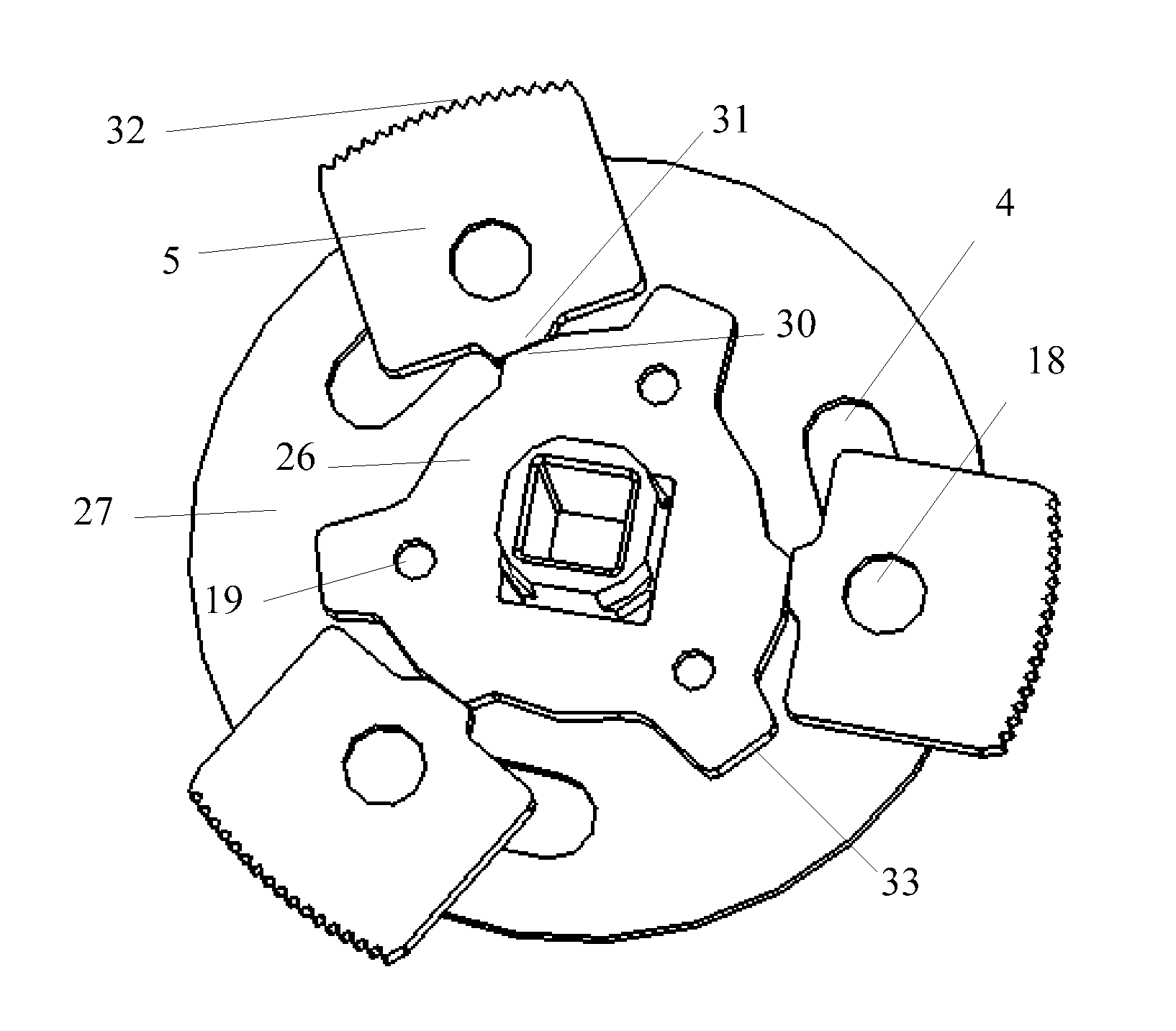
[0028]Three sliders are adopted in this embodiment. As shown in FIGS. 4 and 5, a locking cam 26 is connected with an unlocking cam 27 through respective semi-punched bosses 19 on the locking cam 26. Sliders 5 are connected with three symmetrical cam grooves 4 on the unlocking cam 27 through respective semi-punched bosses 18 on the sliders 5. A self-locking is formed between each self-locking surface 31 of the sliders 5 and each self-locking surface 30 of the locking cam 26.

[0029]When the angle-regulation of a recliner is realized through the recliner regulating device having the configuration of above mentioned three sliders, engagement between the teeth will become more stable and flexible. The recliner regulating device adopting three sliders will be described in detail...


PUM


Abstract

Described herein is a recliner regulating device comprising a locking cam, an unlocking cam with a thickness less than the locking cam, a ratchet gear, a coulisse and a return spring connected with a central shaft. The locking cam is connected with the unlocking cam. Sliders are connected with the unlocking cam and sliding grooves. A jacket is connected with the ratchet gear and the coulisse. The return spring is connected with the coulisse. The thickness of the locking cam and the unlocking cam may be respectively designed in terms of the stress applied thereon. Since the locking cam and the unlocking cam are separately produced, structure of the die is simplified and service life of the die is improved significantly. The locking cam and the unlocking cam may be manufactured by punch, which leads to a greater production efficiency.

Description

CROSS-REFERENCES TO RELATED APPLICATIONS[0001]This application claims the benefit of Chinese Application No. 200710079391.0 filed Feb. 16, 2007.STATEMENT REGARDING FEDERALLY SPONSORED RESEARCH OR DEVELOPMENT[0002]Not applicable.BACKGROUND OF THE INVENTION[0003]This invention relates to the field of mechanical technology, in particular to a recliner regulating device.[0004]At present, functions of angle-regulating and back's quick-folding may be realized in most of the recliner which then will be locked up after the angle-regulating is completed so as to fix the angle between the recliner seat and the recliner back.[0005]There are mainly two modes to achieve angle-regulating in the prior arts. The first mode is disclosed for example in Chinese Utility Model Patent No. 200420017699.4 titled “Plate spring type armchair angle regulating and back folder nuclear installation”. As shown in FIG. 1, two-slider configuration is adopted in this device to realize the angle-regulating. This devi...

Claims


Application Information

Patent Timeline
Patent Type & Authority Patents(United States)
IPC IPC(8): F16H53/00
CPCB60N2/2356Y10T74/2101B60N2/236
Inventor LUO, XIANHUHUANG, ZHENGKUN
Owner HUBEI AVIATION PRECISION MASCH TECH CO LTD
Why Eureka
Try Eureka