[0023] In order to explain the embodiments of the present application or the technical solutions in the prior art more clearly, the embodiments will be briefly introduced below.
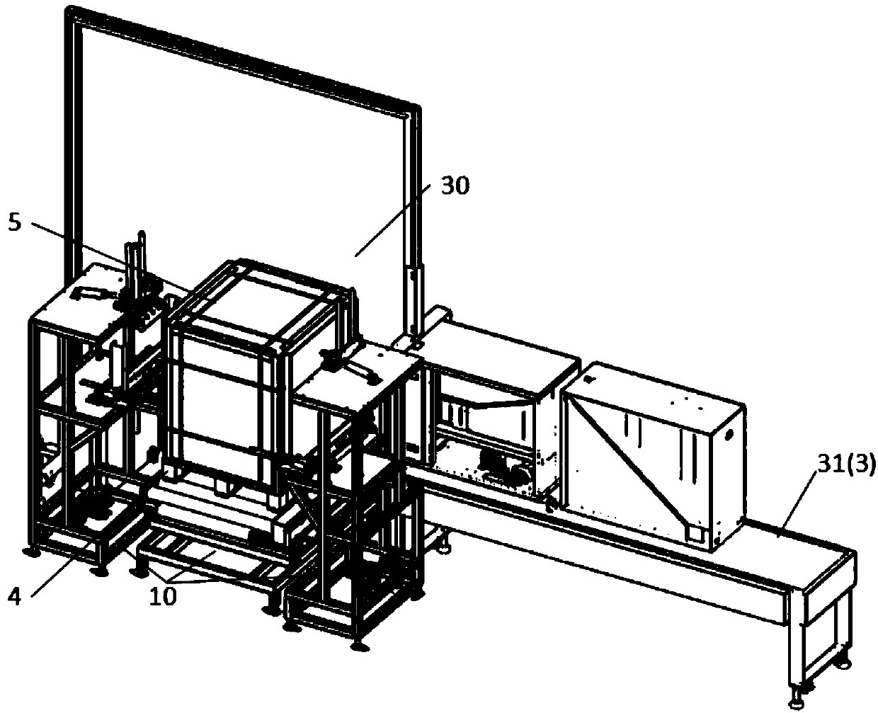
[0024] Such as Figure 1-14 , An automatic pallet corner guard placement machine, used to place the top and side corner guards 6 of the rectangular packing box 5, and combined with the threading baler 3, the threading baler 3 includes a longitudinal threading baler 31. The traversing strapping machine 32 has a packing area 30 in the threading strapping machine, and the bottom four edges of the packing box 5 are placed on the bottom pallet 4;
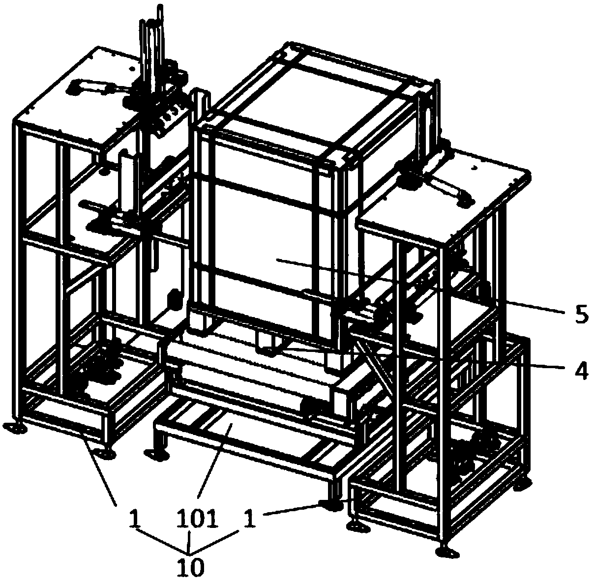
[0025] The automatic pallet corner guard placement machine includes a top corner guard placement machine 10 for top four-edge corner guard placement and a side corner guard placement machine 20 for side four-edge guard corner placement. The top corner guard placement machine 10 and The side corner protector placement kit 20 is used in combination with the longitudinal threading strapping machine 31 and the cross cording baler 32; the top corner guard placement kit 10 includes a bottom circulation seat 101 located in the middle of the packing area and a pair of bottom circulation seats. The top corner protector unit 1 on opposite sides of the seat 101, the bottom pallet 4 and the packing box 5 are placed on the bottom circulation seat 101; the side corner protector placement kit 20 includes a bottom fixing device located in the middle of the packing area 30 The base 201 and 4 side corner protection stand-alone machines 2 arranged around the bottom fixing base 201, the bottom pallet 4 and the packing box 5 are placed on the bottom fixing base 201;
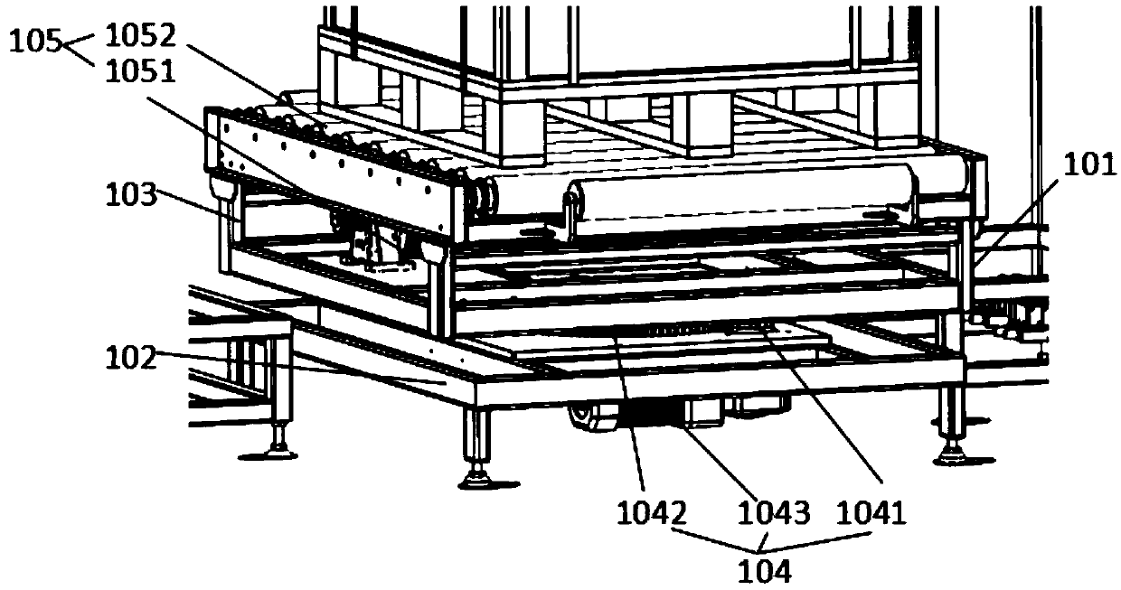
[0026] The bottom rotating seat 101 includes a lower seat 102, an upper seat 103, a rotating mechanism 104, and a flow mechanism 105. The upper seat 103 is located above the lower seat 102. The rotating mechanism 104 includes a rotating motor 1043, a first-stage gear 1041, A secondary gear 1042, a secondary gear 1042 is fixed at the bottom of the upper seat 103, the lower end of the secondary gear 1042 is matched with the lower seat 102 with a shaft, one side of the secondary gear 1042 is matched with a primary gear 1041, the primary gear 1041 Driven by a rotating motor 1043 installed at the lower part of the lower base 102; the flow mechanism 105 includes a flow drive motor 1051, a roller 1052, a plurality of rollers 1052 are installed on the upper base 103, the upper end carries the packing box 5, the roller 1052 is installed on The flow drive motor 1051 at the lower part of the upper base 103 drives the rotation; the bottom fixed base 201 includes a fixed base 202 and a second flow mechanism 205 arranged on the fixed base 202. The structure of the second flow mechanism 205, various components and the components The location layout is the same as that of the mobile organization;
[0027] The top corner protector unit 1 includes a vertical main support 110 divided into three layers: lower, middle, and upper. The lower layer of the longitudinal main support 110 is provided with an electrical control unit 7, and the middle and one side of the longitudinal main support 110 are provided with top corners. A limit mechanism 13 is arranged on the other side of the accommodating groove 12, and a top corner guard installation claw 14 is arranged on the upper layer of the longitudinal main support 110; under the control of the electric control unit 7, the limit mechanism 13 assists in positioning, and the top corner guard installation claw 14 Grab the corner protection 6 in the top corner protection accommodating groove 12 and place it on the top four edges of the packing box 5;
[0028] The top angle protection mounting claw 14 includes a main shaft frame 141, a lever mechanism 142, a telescopic mechanism 143, and a claw head 144. The main shaft frame 141 includes shaft seats 1411 distributed on both sides of the upper front end of the longitudinal main frame 110. The main shaft 145 passes through the shaft seat 1411 and rotates around the rotating frame 1412. The lever mechanism 142 includes a lever cylinder 1421, a transmission plate 1422. One side of the transmission plate 1422 is connected to the main shaft 145, and the other end is connected to the lever cylinder. The piston rod of 1421 is hinged, and the cylinder of the lever cylinder 1421 is hinged to the rear side of the shaft seat 1411; the transmission plate 1422, the lever cylinder 1421 is located at the end of the main shaft 145, and the transmission plate 1422 is provided with an adjusting groove 1423, and Use fasteners to adjust the distance between the hinge point of the transmission plate 1422 and the piston rod of the lever cylinder 1421 and the connection point of the main shaft 145; the telescopic mechanism 143 includes a telescopic cylinder 1431, a guide block 1432, and a guide rod 1433, so The claw head 144 includes a claw frame 1441 and a claw body 1442. The cylinder tube of the telescopic cylinder 1431 is connected to the middle of the turret 1412. A pair of guide blocks 1432 are symmetrically distributed on both sides of the telescopic cylinder 1431. Each guide block 1432 is matched with a guide rod 1433. , The end of the piston rod of the telescopic cylinder 1431 and the end of the guide rod 1433 on the same side are connected to the claw frame 1441; the end of the claw frame 1441 is hinged with the claw body 1442 through a horizontal axis, the claw body 1442 includes a "V The two claw pieces 1443 connected by the word ", each claw piece 1443 is provided with a suction cup 1444; the end of each claw piece 1443 of the claw head 144 is also provided with a guide wheel 1445 that rotates around a horizontal axis of rotation. A torsion spring 1446 is passed through the horizontal shaft at the end of the claw frame 1441;
[0029] The top corner protection accommodating groove 12 includes a accommodating bottom plate 121 and accommodating bars 122 vertically arranged at both ends of the accommodating bottom plate 121. The corner protection 6 is placed between the accommodating bars 122, and the limit mechanism 13 includes a limit The bottom plate 131, the limit cylinder 132, and the limit end plate 133. The limit bottom plate 131 is fixed to one end of the accommodating bottom plate 121. The cylinder tube of the limit cylinder 132 is hinged to the rear of the limit bottom plate 131. The limit cylinder The piston rod of the 132 is hinged with the end of the limit end plate 133 which is also hinged to the front end of the limit bottom plate 131. Under the action of the limit cylinder 132, the limit end plate 133 is deflected by 90° to realize the horizontal-vertical switch. Blocking limit; each limit mechanism 13 limit cylinder 132, limit end plate 133 combination can have 1 to 3 pairs, preferably 2 pairs; the limit mechanism 13 function is, if the box is not a standard quadrangular prism, But for a general cuboid, the top four edges are in different positions. After rotation, the distance of forward movement causes the deviation of the corner guard 6, which can be corrected by the limit mechanism 13;
[0030] An anti-friction plate 124 is provided at the lower end of the accommodating bottom plate 121, which is fitted to the middle layer of the longitudinal main support 110. The middle layer of the longitudinal main support 110 is also hinged with a cylinder of a transverse cylinder 123, and the piston rod and the container of the transverse cylinder 123 Set the bottom plate 121 to be hinged;
[0031] Above, the various actuators of the top corner protection stand-alone 1 and the bottom rotation seat 101, including the cylinders, motors, and the suction cups 1444 of the top corner protection mounting claw 14, are controlled by the electrical control unit for power supply, air supply and program control;
[0032] The side corner protector unit 2 includes a horizontal main bracket 210, a second electrical control part 8 is arranged at the lower part of the horizontal main bracket 210, a side protector accommodating groove 22 is arranged on one side of the upper side of the horizontal main bracket 210, and a side protector is arranged on the other side. The corner protection installation claws 24, under the control of the second electrical control part 8, the side protection corner installation claws 24 grab the corner protection 6 in the side protection corner accommodating groove 22 and place it on the side four edges of the packing box 5; The side angle protector unit 2 has two types, which are distinguished according to the type (A type and B type) of the lateral main bracket 210 to install different side angle protector mounting claws 24; the preferred solution is that on the front side of the cross-line baler 32 Install a pair of A-type side bead mounting claws 24, and install a pair of B-type side bead mounting claws 24 across the rear side of the line baler 32; this can save space and improve operation fluency and efficiency;
[0033] For example, the A-type side angle protection mounting claw 24 includes a vertical frame 240, a second main shaft frame 241, a second lever mechanism 242, a second telescopic mechanism 243, and a second claw head 244. , The vertical frame 240 is vertically connected to the upper part of the horizontal main frame 210 and one side of the side protector accommodating groove 22, the second main shaft frame 241, the second lever mechanism 242, the second telescopic mechanism 243, and the second claw The head 244 is arranged on the vertical frame 240, and its structure is the same as that of the main shaft frame 141, the lever mechanism 142, the telescopic mechanism 143, and the claw head 144 respectively. The second claw head 244 faces the side corner accommodating groove 22, In terms of spatial layout, it is equivalent to placing the top corner protector mounting claw 14 from horizontal to vertical with the main rotating shaft 145 of the turret 1412 as a reference;
[0034] For example, the side bead mounting pawl 24 of type B includes a rotating frame 250, a third telescopic mechanism 253, and a third claw head 254. The rotating frame 250 includes a horizontal part 2501 and a vertical part. 2502, the horizontal portion 2501 is arranged on the horizontal main support 210 and is driven to rotate by the horizontal rotation motor 211, the third telescopic mechanism 253 and the third claw head 254 are arranged on the vertical portion 2502 of the rotating frame 250, and the third telescopic mechanism 253, The structure of the three-claw head 254 is the same as the telescopic mechanism 143 and the claw head 144 respectively;
[0035] Regardless of type A or B, the side protector mounting claws 24 are equipped with a side protector accommodating groove on the side angle protector unit 2 to which they belong, and the side protector accommodating groove 22 includes a vertical installation on the horizontal main support The accommodating side plate 221 and the second accommodating fence 222 vertically arranged at the upper and lower ends of the accommodating side plate 221;
[0036] Above, the individual actuators of the side corner protector unit 2 and the bottom fixing base 201, including cylinders, motors, and the suction cups 1444 of the side corner protector mounting claws 24, are controlled by the second electrical control unit 8 for power supply, air supply and program control.
[0037] The above embodiments are only used to illustrate the preferred technical solutions of the present invention. It should be pointed out that for those of ordinary skill in the art, without departing from the principle of the present invention, several improvements or equivalent replacements are considered It is the protection scope of the present invention and should still be covered in the scope of the claims of the present invention.