High accuracy optical pointing apparatus

a high-accuracy, optical pointing technology, applied in the direction of mountings, telescopes, instruments, etc., can solve the problems of ineffective azimuth gimbals, inability to track them by spinning the azimuth axis, loss of control of a second direction, etc., to achieve optimal two-axis beam pointing control, avoid high acceleration, and eliminate gimbal locks

a high-accuracy, optical pointing technology, applied in the direction of mountings, telescopes, instruments, etc., can solve the problems of ineffective azimuth gimbals, inability to track them by spinning the azimuth axis, loss of control of a second direction, etc., to achieve optimal two-axis beam pointing control, avoid high acceleration, and eliminate gimbal locks

US7894144B2Active Publication Date: 2011-02-22BAE SYST INFORMATION & ELECTRONICS SYST INTEGRATION INC

Image

  • High accuracy optical pointing apparatus
  • High accuracy optical pointing apparatus
  • High accuracy optical pointing apparatus

Examples


Embodiment Construction

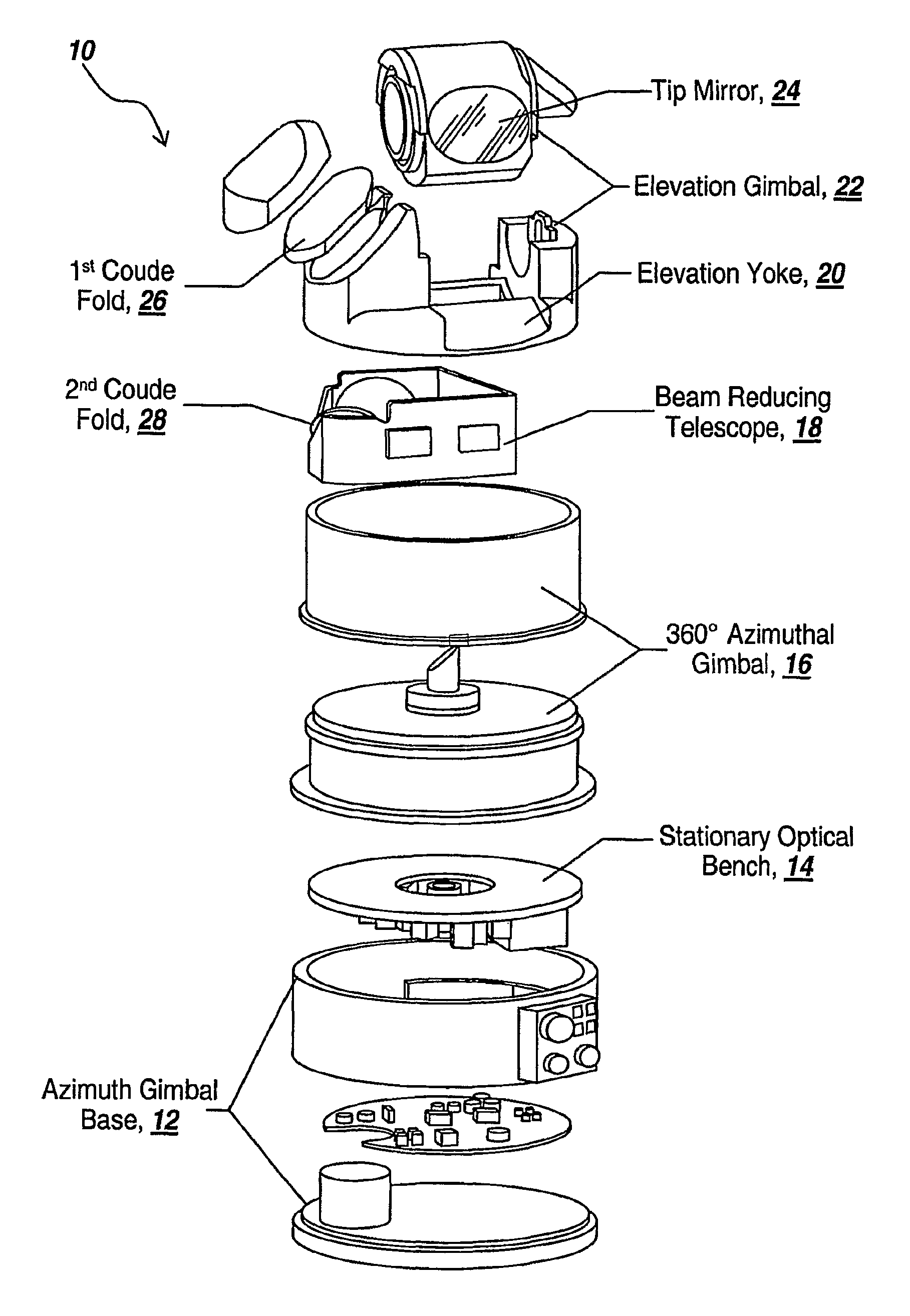
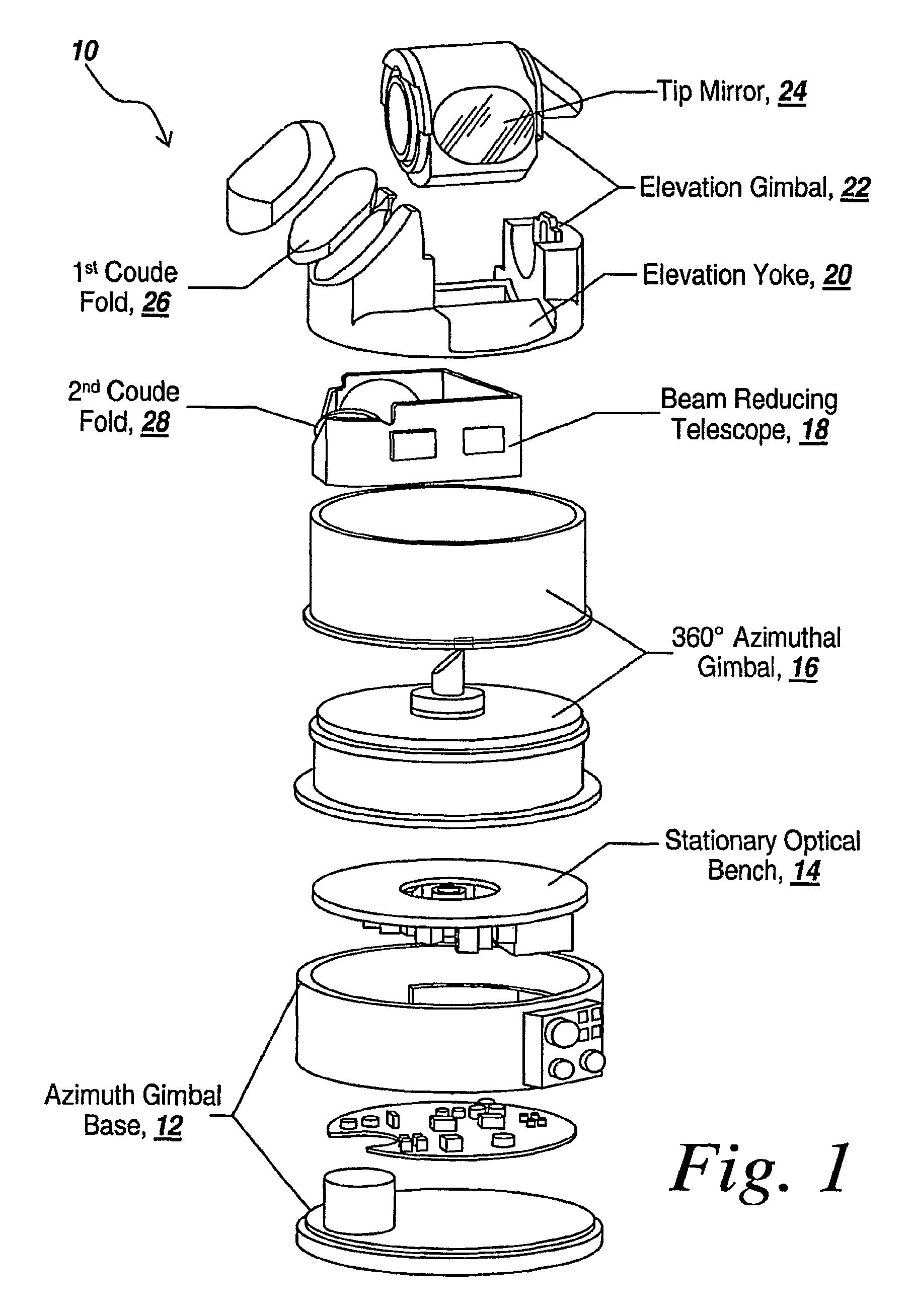
[0044]Referring to FIG. 1, what is provided by the subject system is a three-axis beam director or receiver that provides hyper-hemispherical coverage, avoids the gimbal lock typical of El-over-Az beam directors and allows unobscured use of the full aperture. The three-axis system comprises a 360-degree azimuthal gimbal 16, a preferably + / โˆ’180 degree elevation gimbal 22, and a tip minor 24, located above the El-over-Az combined gimbals. The tip mirror preferably provides ยฑ10-degree tracking perpendicular to the elevation gimbal motion.

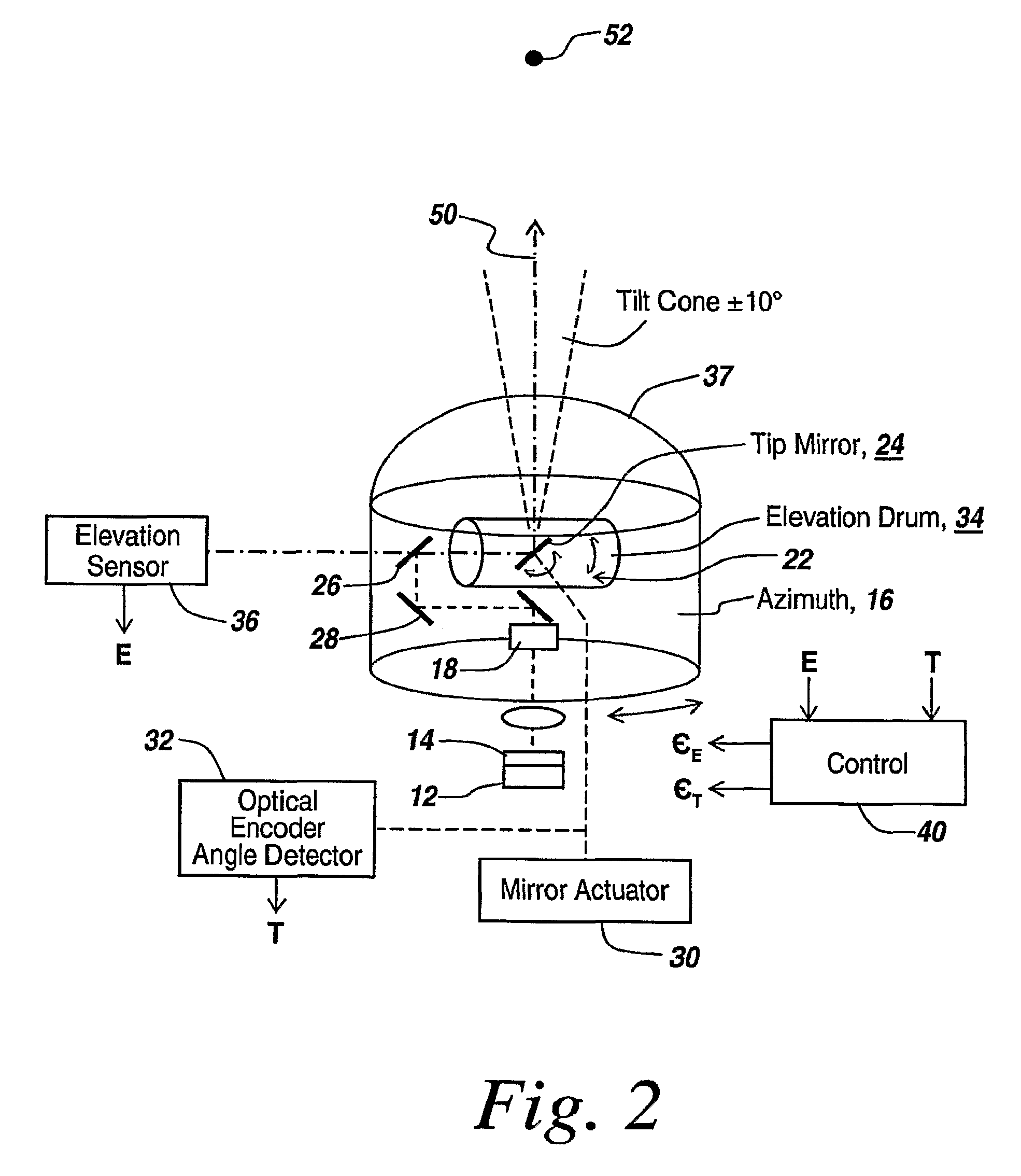
[0045]Tip mirror 24 and high-bandwidth elevation gimbal 22 operate as a high speed, 2-axis pointing system. Inside a predetermined cone, preferably a 10-degree half angle cone centered at zenith, they provide all pointing functions. Beyond this cone, the elevation gimbal provides high-bandwidth pointing over its full range, preferably providing pointing over a greater than horizon-to-horizon 220ยฐ range in one axis, with the tip mirror providing high ba...


PUM


Abstract

In the subject three-axis pointing system, the elevation and tip mirror axes are permanently mounted with their rotation axes orthogonal to each other to eliminate gimbal lock over the hemisphere, to avoid high accelerations as the zenith or nadir pointing directions are approached, and to provide optimal two-axis beam pointing control.

Description

RELATED APPLICATIONS[0001]This Application claims rights under 35 USC ยง119(e) from U.S. Application Ser. No. 60 / 804,297 filed Jun. 9, 2006, the contents of which are incorporated herein by reference.FIELD OF THE INVENTION[0002]This invention relates to the field of optical pointing and tracking systems, and more particularly to optical pointing and tracking systems that require high-speed pointing and high accuracy over a large field of regard.BACKGROUND OF THE INVENTION[0003]Three-axis gimbal-based beam director and receiver systems in general provide a hemispherical field of regard and in some instances a hyper-hemispherical field of regard, which refers to a field of regard greater than 180 degrees.[0004]Borrowing from astronomical telescopes, it is a requirement that the telescope be able to point anywhere in the sky. In order to do that, a two-axis system is employed that points the telescope utilizing an azimuth gimbal that rotates the telescope around in a horizontal directio...

Claims


Application Information

Patent Timeline
22 Feb 2011
Publication
US7894144B2
IPC
G02B7/02
CPC
F41G3/22; G02B23/06; G02B26/105; G02B27/644
Inventors
WEIN, STEVEN J.; TARGOVE, JAMES D.