
High accuracy optical pointing apparatus

a high-accuracy, optical pointing technology, applied in the direction of mountings, telescopes, instruments, etc., can solve the problems of ineffective azimuth gimbals, inability to track them by spinning the azimuth axis, loss of control of a second direction, etc., to achieve optimal two-axis beam pointing control, avoid high acceleration, and eliminate gimbal locks

Active Publication Date: 2010-09-02
BAE SYST INFORMATION & ELECTRONICS SYST INTERGRATION INC
View PDF5 Cites 14 Cited by
  • Summary
  • Abstract
  • Description
  • Claims
  • Application Information

AI Technical Summary

Benefits of technology

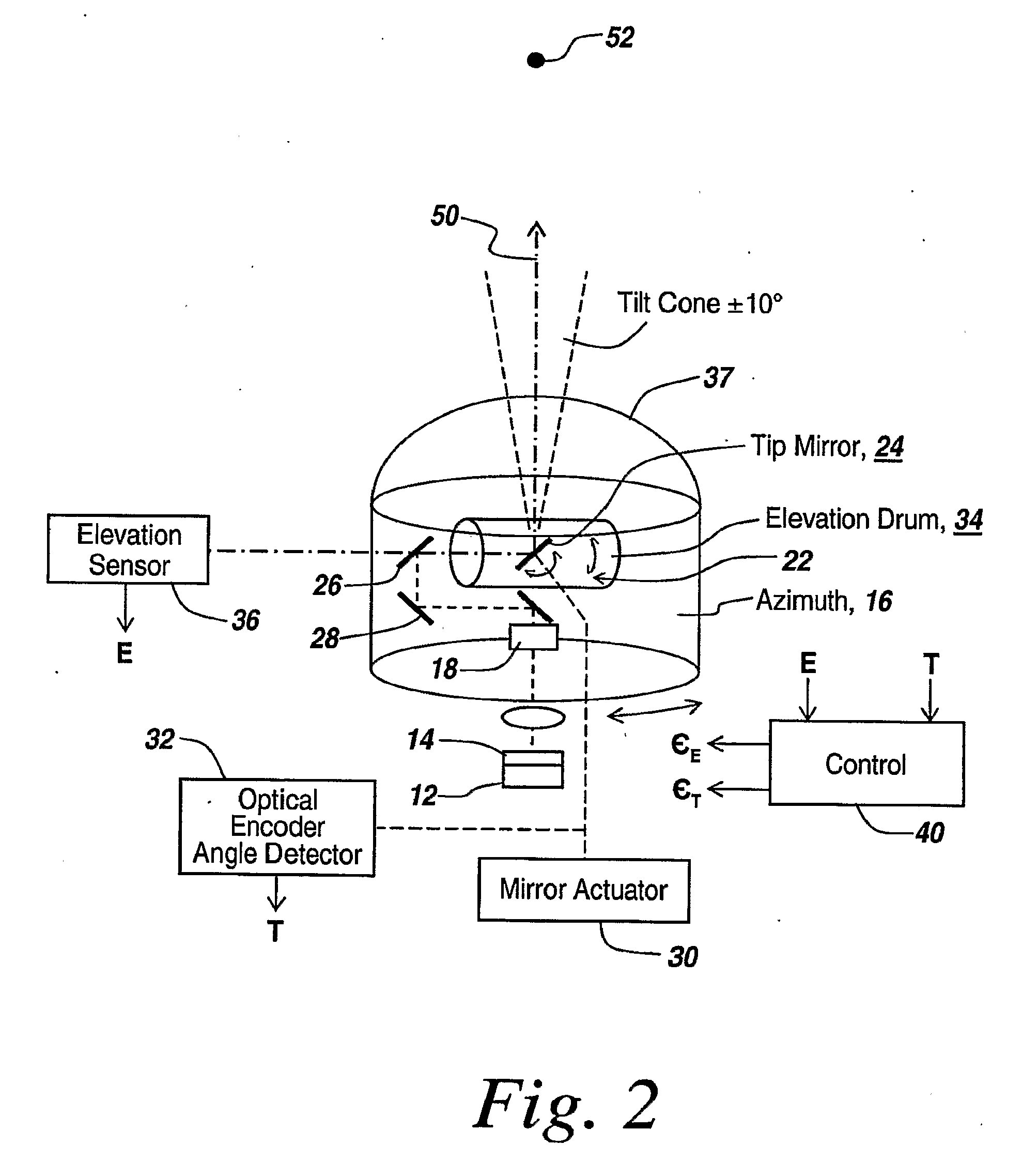
[0028]Rather than utilizing three-axis gimbal systems involving a massive third gimbal and complicated control algorithms to avoid gimbal lock, in the subject system a tip mirror is mounted to an elevation gimbal such that the axis of rotation of the tip mirror is always orthogonal to the axis of rotation of the elevation gimbal. This provides two-axis control about the pointing direction of the pointing system, which it has been found eliminates gimbal lock when pointing anywhere in the hemisphere when the range of the tip mirror is limited to less than 90 degrees.
[0029]The use of an orthogonally oriented tip mirror and elevation gimbal also permits de-coupling of the tip mirror axis from the elevation gimbal axis to simplify pointing control. Moreover, when the elevation gimbal and the tip mirror are made of lightweight materials, inertia is minimized and bandwidth is maximized to provide a two-axis pointing system having a high bandwidth and low inertia for improved stabilization and jitter control.

Problems solved by technology

The problem in controlling such a telescope is the ability to point. at a position in space that is located straight up (zenith) or straight down (nadir).
As a result, the ability to control a second direction is lost when pointing straight up or straight down.
The result is that if one is trying to track an object that is directly overhead or close to overhead, the azimuth gimbal is ineffective to move the telescope pointing direction.
Thus, when a target is at the zenith, one cannot track it by spinning the azimuth axis.
When looking in this direction, one cannot track or stabilize in other directions.
As a result, if one is tracking an object that is at or near the zenith of the system, one cannot track in a direction that is orthogonal to the elevation axis.
However, if the object to be stabilized on is directly above or below the gimbaling system, one can only stabilize on one axis or equivalently, in only one direction.
As a result one loses the ability to stabilize the line of sight of the system along a second direction.
Where one has an accidental lineup, one only has two axes available, which again reverts to the two-axis gimbal lock problem.
While control algorithms exist to make sure that the third axis does not result in the lining up of any two axes, installing a third gimbal in the past has added increased weight and considerably more mechanical complexity.
Thus, if one provides a third gimbal within the other two gimbals, the gimbal system tends to be heavy and the positioning is not particularly rapid due to the mass of the third gimbal.
Thus, these three-gimbal systems suffer from reduced bandwidth and increased inertia.
Also, providing a third gimbal occupies a considerable amount of volume.
Moreover, while it is theoretically possible in conventional three-axis mechanical gimbaling configurations to push the gimbal lock to 90 degrees away or to some other point where gimbal locking is not a problem, i.e., to move the gimbal lock position to regions or locations that are not of interest, such gimbal lock positioning is not always possible.

Method used


Image

  • High accuracy optical pointing apparatus
  • High accuracy optical pointing apparatus
  • High accuracy optical pointing apparatus

Examples


Embodiment Construction

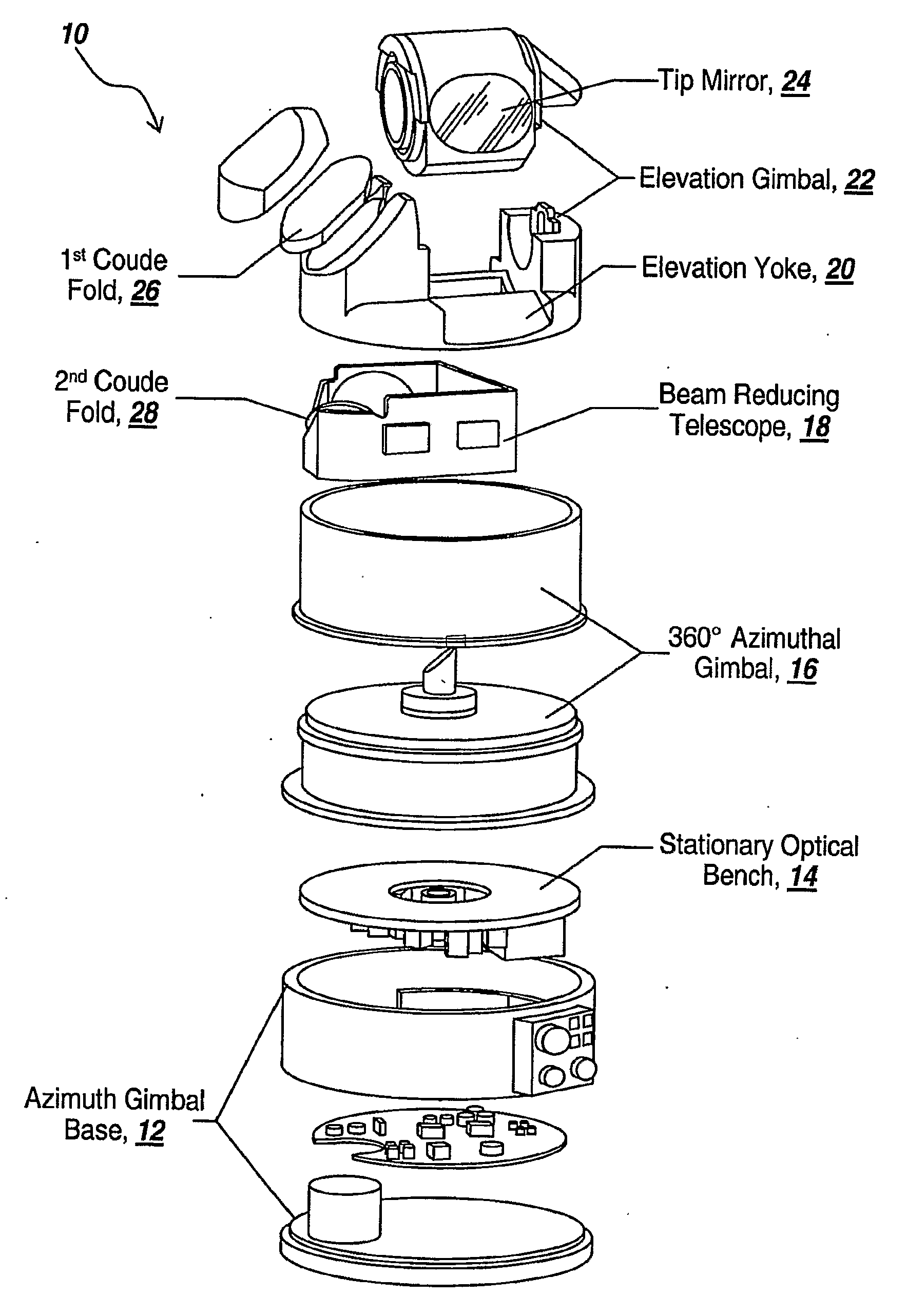
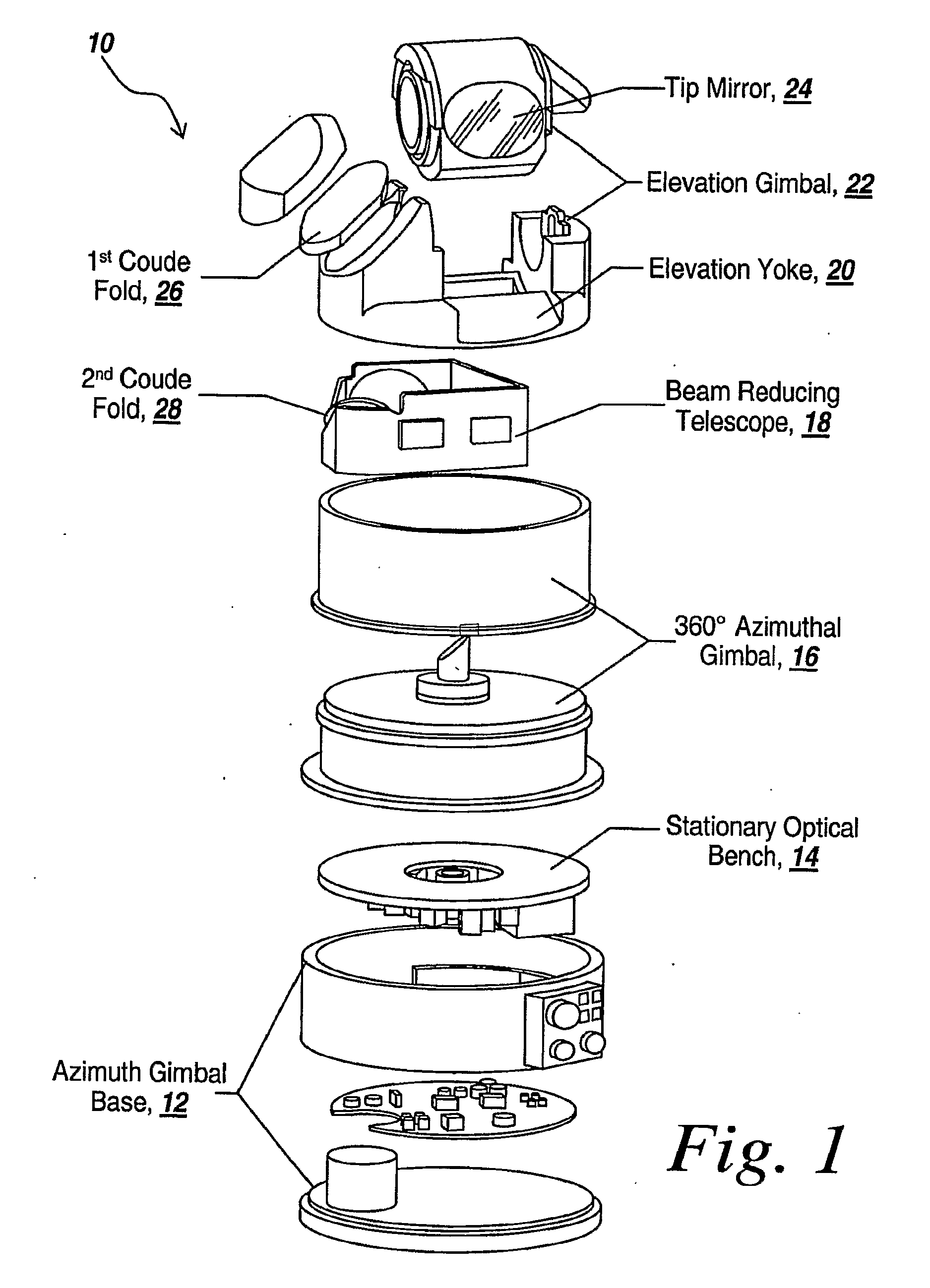
[0044]Referring to FIG. 1, what is provided by the subject system is a three-axis beam director or receiver that provides hyper-hemispherical coverage, avoids the gimbal lock typical of El-over-Az beam directors and allows unobscured use of the full aperture. The three-axis system comprises a 360-degree azimuthal gimbal 16, a preferably + / −180 degree elevation gimbal 22, and a tip minor 24, located above the El-over-Az combined gimbals. The tip mirror preferably provides ±10-degree tracking perpendicular to the elevation gimbal motion.

[0045]Tip mirror 24 and high-bandwidth elevation gimbal 22 operate as a high speed, 2-axis pointing system. Inside a predetermined cone, preferably a 10-degree half angle cone centered at zenith, they provide all pointing functions. Beyond this cone, the elevation gimbal provides high-bandwidth pointing over its full range, preferably providing pointing over a greater than horizon-to-horizon 220° range in one axis, with the tip mirror providing high ba...


PUM


Abstract

In the subject three-axis pointing system, the elevation and tip mirror axes are permanently mounted with their rotation axes orthogonal to each other to eliminate gimbal lock over the hemisphere, to avoid high accelerations as the zenith or nadir pointing directions are approached, and to provide optimal two-axis beam pointing control.

Description

RELATED APPLICATIONS[0001]This Application claims rights under 35 USC §119(e) from U.S. application Ser. No. 60 / 804,297 filed Jun. 9, 2006, the contents of which are incorporated herein by reference.FIELD OF THE INVENTION[0002]This invention relates to the field of optical pointing and tracking systems, and more particularly to optical pointing and tracking systems that require high-speed pointing and high accuracy over a large field of regard.BACKGROUND OF THE INVENTION[0003]Three-axis gimbal-based beam director and receiver systems in general provide a hemispherical field of regard and in some instances a hyper-hemispherical field of regard, which refers to a field of regard greater than 180 degrees.[0004]Borrowing from astronomical telescopes, it is a requirement that the telescope be able to point anywhere in the sky. In order to do that, a two-axis system is employed that points the telescope utilizing an azimuth gimbal that rotates the telescope around in a horizontal directio...

Claims


Application Information

Patent Timeline
IPC IPC(8): G02B23/02G02B7/198
CPCF41G3/22G02B27/644G02B26/105G02B23/06
Inventor WEIN, STEVEN JTARGOVE, JAMES D.MENIKOFF, ARTHURBOWLER, DENNIS P.KORWAN, DAVID J.
Owner BAE SYST INFORMATION & ELECTRONICS SYST INTERGRATION INC
Learn More