
LED replacement lamp and a method of replacing preexisting luminaires with LED lighting assemblies

a technology of led replacement lamps and led lighting assemblies, which is applied in the manufacture of electrode systems, defective tube/lamp repair/regeneration, and light support devices, etc., can solve the problems of insufficient thermal heat sinking and high initial investment cost of led illumination, and achieve the effects of reducing light pollution, reducing visibility, and energy was

Active Publication Date: 2010-06-03
SIGNIFY HLDG BV
View PDF100 Cites 58 Cited by
  • Summary
  • Abstract
  • Description
  • Claims
  • Application Information

AI Technical Summary

Benefits of technology

[0009]One embodiment of the invention is comprised of a shaped plate that fits in the existing opening of a luminaire. The plate has a recessed portion to accommodate light bars or a light plate that is comprised of a plurality of LEDs with optics combined with each LED in an array to provide a predetermined light output pattern. The recess provides a shadowed zone of light from the LEDs and / or optics that prevents the light from extending around said opening of the luminaire. This allows the luminaire to meet the Dark Sky Initiative standards required in many regions of the world for outdoor lighting.

Problems solved by technology

The initial investment cost of LED illumination is expensive when compared with traditional lighting means using the parameter of cost / lumen as the metric, even though the cost / lumen-hour or cost / lumen-lifetime-hours is substantially less than incandescent lighting when operating expenses are included.
This technique does not offer enough thermal heat sinking to provide a sufficient amount of light for competitive use in the marketplace.

Method used


Image

  • LED replacement lamp and a method of replacing preexisting luminaires with LED lighting assemblies
  • LED replacement lamp and a method of replacing preexisting luminaires with LED lighting assemblies
  • LED replacement lamp and a method of replacing preexisting luminaires with LED lighting assemblies

Examples


Embodiment Construction

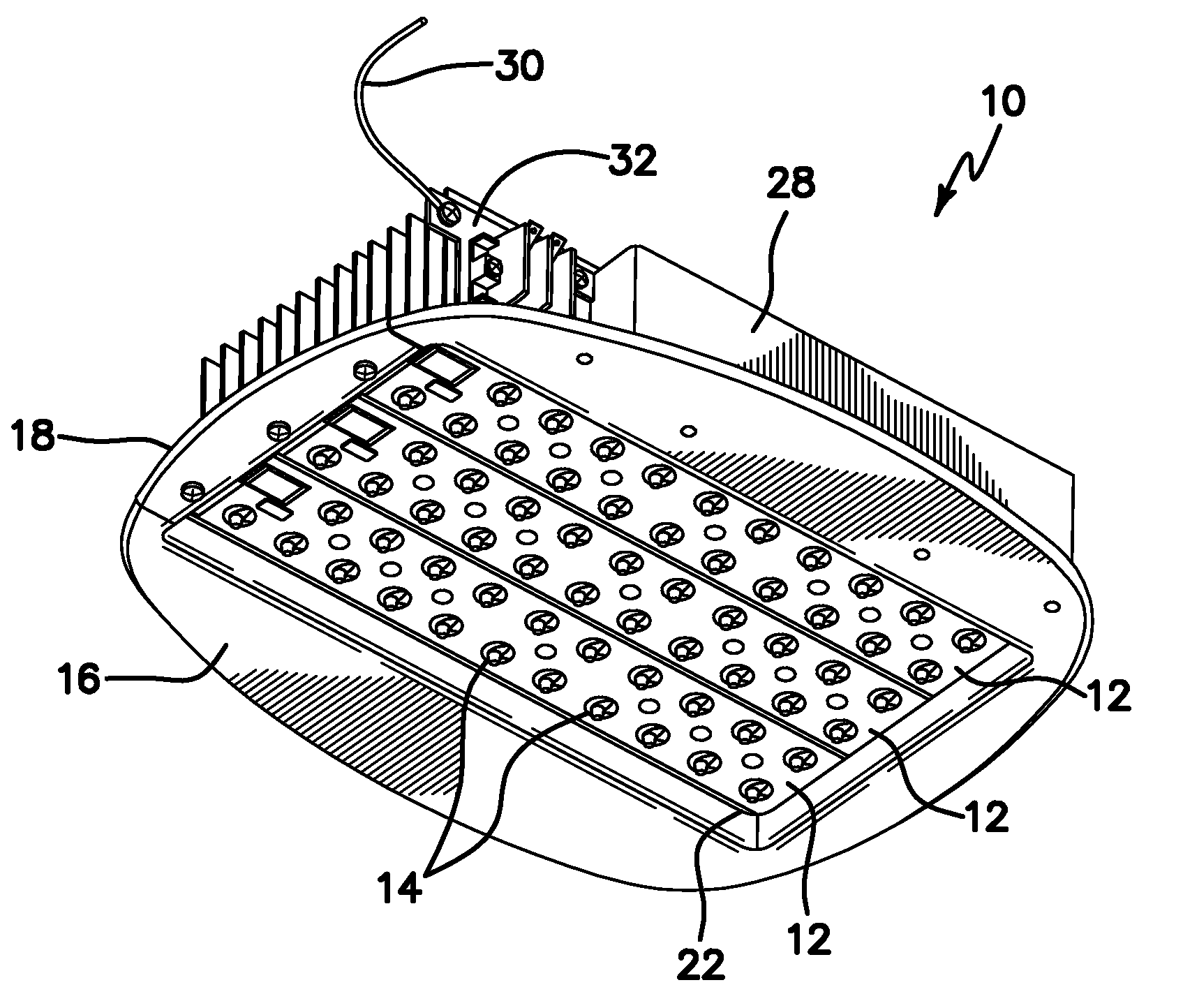
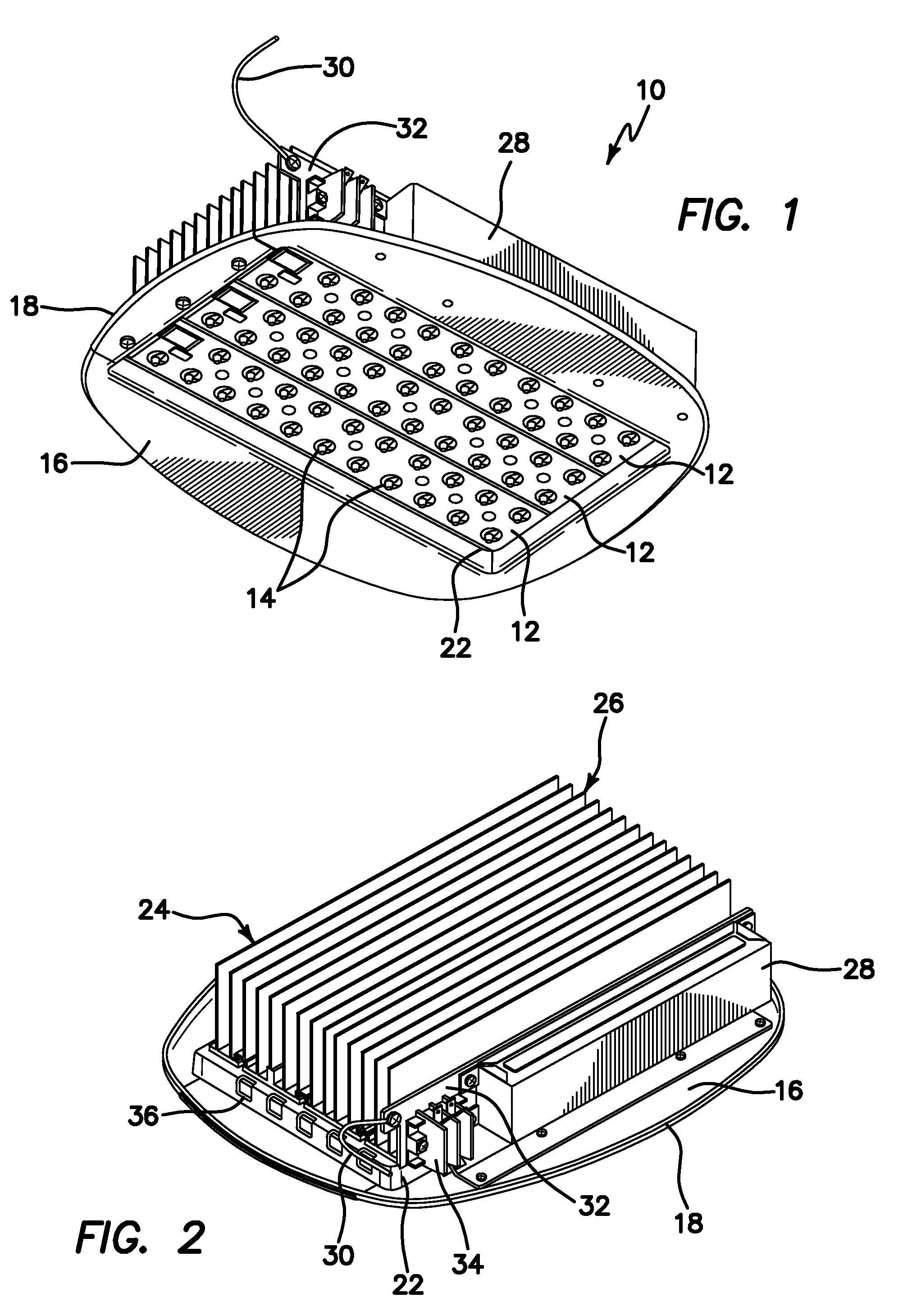
[0026]LED lighting module, generally denoted by reference numeral 10, is shown in perspective view in FIG. 1 wherein the lower or outside light aperture is turned facing the viewer of the drawing. Module 10 includes a plurality of light bars 12, such as those manufactured by Cooper Lighting, LLC. As will be described below, module 10 is scalable in the sense that it may be configured to selectively incorporate one, two or three light bars without an alteration in the design. Light bars 12 may include any type of array now known or later devised, but are each light bar 12 is shown as including a double row optically lensed LEDs or LED packages 14 (hereinafter referenced collectively as LED or LEDs). It is to be expressly understood that wherever “light bar” or “light bar array” is used in the specification, it is meant to include, but is not limited to any type of planar or two-dimensional array of LEDs, including non-rectilinear arrays.

[0027]In the illustrated embodiment of FIG. 1, ...


PUM

PropertyMeasurementUnit
perimeteraaaaaaaaaa
heataaaaaaaaaa
coloraaaaaaaaaa

Abstract

A lighting apparatus for retrofitting an existing luminaire includes a plurality of light emitting diodes (LED) of similar or differing wavelengths arranged and configured in at least one light bar array, a heat sink module thermally coupled to the at least one light bar array, an electronic power module electrically coupled to the at least one light bar array, and a plate coupled to the at least one light bar array, electronic power module and the heat sink module, the plate arranged and configured for coupling to the luminaire to provide quick and easy installation and replacement of the at least one light bar array, heat sink module and electronic power module into and from the luminaire.

Description

RELATED APPLICATIONS[0001]The present application is related to U.S. Provisional Patent Application Ser. No. 61 / 119,487, filed on Dec. 3, 2008, which is incorporated herein by reference and to which priority is claimed pursuant to 35 USC 119.BACKGROUND OF THE INVENTION[0002]Embodiments of the invention relate generally to the field of general lighting illumination and more particularly to the field of apparatus and methods for using light emitting diodes (LEDs) or other light sources in a replacement lamp module.[0003]The initial investment cost of LED illumination is expensive when compared with traditional lighting means using the parameter of cost / lumen as the metric, even though the cost / lumen-hour or cost / lumen-lifetime-hours is substantially less than incandescent lighting when operating expenses are included.[0004]Therefore, if a significant portion of the cost of a new lighting fixture for the LED can be eliminated by allowing for use of conventional lighting fixtures, LED l...

Claims


Application Information

Patent Timeline
Patent Type & Authority Applications(United States)
IPC IPC(8): H05B37/02H01J9/50
CPCF21K9/00F21V19/001F21V19/045F21V23/00F21V29/004F21W2131/103Y10T29/49002F21Y2105/001H05B33/0803Y02B20/383F21V23/002F21V29/763F21Y2113/00F21Y2101/02F21Y2105/10F21Y2115/10F21V19/04F21V29/70H05B45/357Y02B20/30
Inventor HOLDER, RONALD G.RHOADS, GREG
Owner SIGNIFY HLDG BV
Learn More