

DMD control method in high dynamic range imaging
A technology with high dynamic range and control method, which is applied in the direction of image communication, color TV parts, TV system parts, etc., can solve the problems of multiple micromirror flipping, achieve the effect of improving accuracy and reducing light pollution
- Summary
- Abstract
- Description
- Claims
- Application Information
AI Technical Summary
Problems solved by technology
Method used
Image

Examples
specific Embodiment approach 1
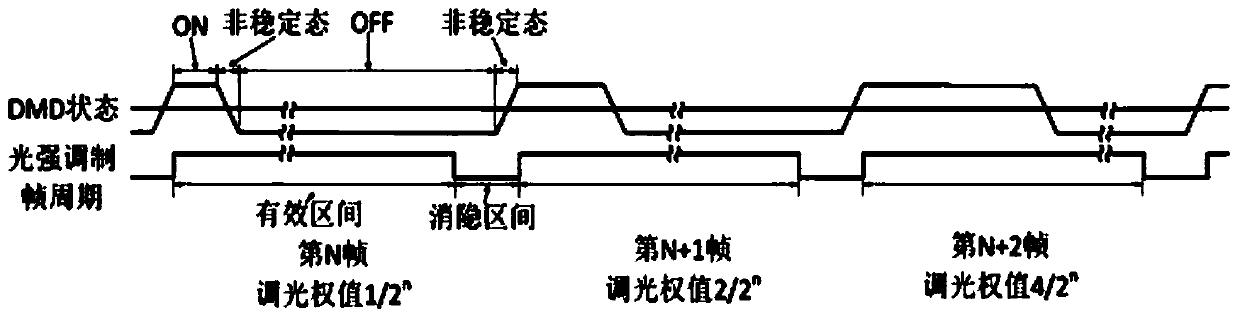
[0022] Specific implementation mode 1. Combination Figure 1 to Figure 3 In this embodiment, the control method of DMD in high dynamic range imaging includes constraints on light intensity modulation weights and constraints on the duration of each bit of the binary value of DMD light intensity modulation weights within one frame time;
[0023] Constraints on light intensity modulation weights:
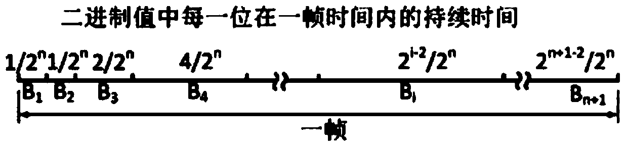
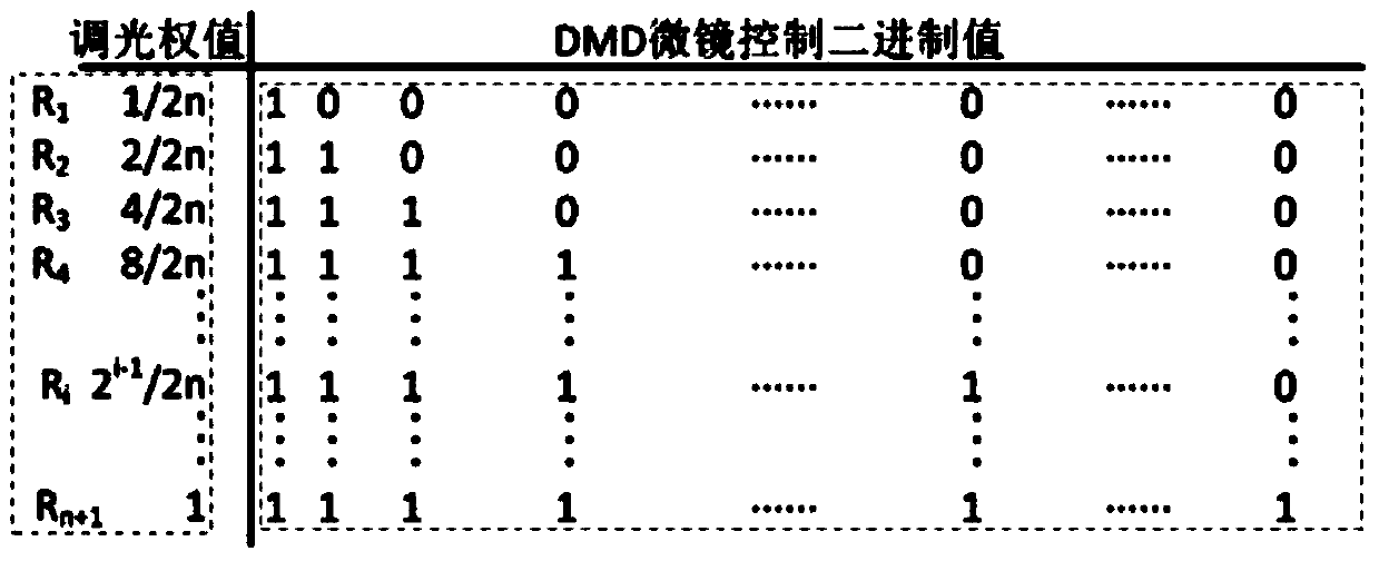
[0024] In high dynamic light intensity modulation, dimming a certain saturated pixel only needs to adjust its pixel value to the sensitive response range of the image detector itself, which is generally the critical saturation value and 1 / 2 critical saturation of the image detector Between values, this is a wide interval, and there is a double relationship between the upper limit and the lower limit of the interval, so the step of the light intensity modulation weight can adopt a double relationship, and the light intensity modulation weight can be set to several fixed values. Set the...
PUM
 Abstract
Description
Claims
Application Information