Small power vertical axle wind-mill generator

A wind-driven generator, vertical axis technology, applied in the direction of wind-driven generator components, wind-powered engines, combined wind-driven motors, etc., can solve problems such as inability to absorb wind energy efficiently, low resistance ratio between forward and reverse winds, difficult home and industrial workshops, etc., to achieve The effective power generation time is long, the floor area is small, and the effect of using less materials

Inactive Publication Date: 2006-09-13
曾碚凯
View PDF0 Cites 8 Cited by
  • Summary
  • Abstract
  • Description
  • Claims
  • Application Information

AI Technical Summary

Problems solved by technology

[0003] In the prior art, a variety of low-power vertical-axis wind turbines for household use have been disclosed, but there are some problems: adjust the windward angle of the sail blades with a fixed mechanism so that the resistance is the largest when the wind is downwind, and the resistance is the smallest when the wind is headed
Some mechanisms for adjusting the

Method used


Image

  • Small power vertical axle wind-mill generator
  • Small power vertical axle wind-mill generator
  • Small power vertical axle wind-mill generator

Examples


Example Embodiment

[0039] Example 1

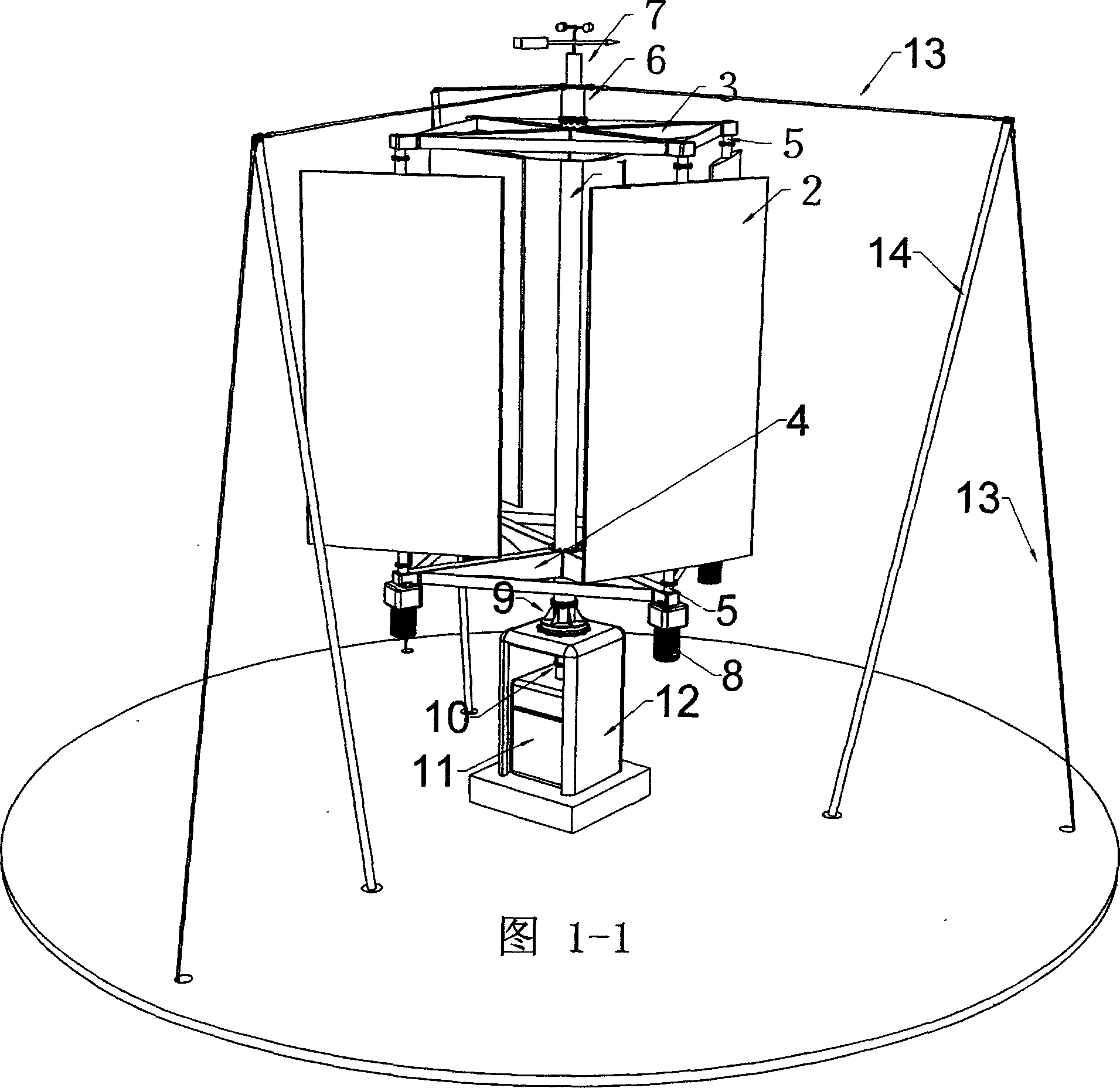
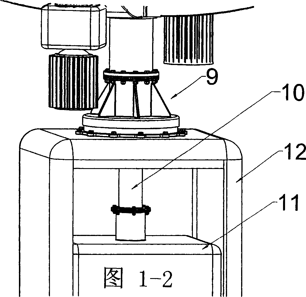
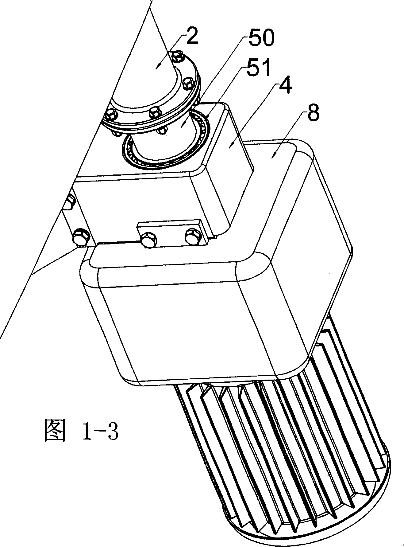
[0040] As shown in Figures 1-1, 1-2, 1-3, 1-4, the low-power vertical-axis wind turbine of the present invention is constructed as follows: the upper and lower ends of the central column 1 are fixedly connected to the upper sail blade support Disk 3 and lower sail blade support disk 4, there are 4 sail blades 2 installed between the two sail blade support disks, each sail blade 2 is rotatably mounted on the upper and lower sails through two upper and lower blade couplings 5 Between leaf support discs 3 and 4. In this embodiment, the lower end of each sail blade 2 is connected to a sail blade windward angle drive mechanism 8 through a sail blade coupling 5; the central column 1 has two rotating support points, one is an anchor 6 at the upper end, and the other is at The lower end is the main bearing 9. They make the central column 1 and all the parts assembled on the central column 1 rotate around the central axis. Each sail blade windward angle drive mechanism 8...

Example Embodiment

[0048] Example 2

[0049] As shown in Fig. 4-1, another method for realizing the central rotating mechanism of the low-power vertical axis wind power generator of the present invention is shown. See Figure 4-2 The anchor 6 is composed of a central shaft 20, a bearing assembly 21, and an anchor plate 22. A central shaft 20 is provided in the center of the anchor plate 22. The lower end of the central shaft 20 has a stop 201 through which the central shaft 20 passes The center column 1 is fixedly mounted on the lower chassis rotation center shaft 904 of the main bearing 9; the upper part of the center shaft 20 is movably mounted with the center column 1 through the bearing assembly 21, and the anchor disk 22 is anchored by the anchor grommet 15 and the steel cable 13. . Therefore, the central shaft 20 is fixedly connected to the main bearing thrust bearing lower chassis 901 during the operation of the wind turbine. The upper end of the center column 1 that rotates with the sail blad...


PUM


Abstract

The invention discloses a low-power vertical wind generator fixed with upper vane and lower vane supporting discs at the upper and lower ends of a center column, respectively, installing plural vanes between the two supporting discs through vane shaft coupling, where the lower end of each vane is connected with a vane windward angle drive mechanism through the vane shaft coupling, the upper end of the center column is connected with an anchor and the lower end of the center column is connected through a main bearing to a base, the main bearing is connected with a generator equipped with reducer through a power transmission mechanism provided with sensor; a wind vane is arranged above the anchor, and the sensor is connected with the windward angle drive mechanism through main controller and the whole is anchored with cable through the anchor, and the main bearing is of a compound pull bearing structure. And it effectively prolongs service life and has strong practicality.

Description

technical field [0001] The invention relates to wind power generation technology, in particular to a low-power vertical-axis wind power generator with composite thrust bearing structure, which can automatically adjust the windward angle of sail blades. Background technique [0002] With the ratification of the Kyoto Protocol by various countries, the world will rapidly expand the demand for clean energy. Wind power is one of the most accessible clean energy for human beings, so it is facing great opportunities for development. The family is the basic unit of social energy demand, so the cleanliness of household energy is of great significance. A lot of domestic wind generators have been disclosed in the known technology, most of which are horizontal axis low-power wind generators. There are also some vertical axis wind turbines. In the case of low power (below 1000W), the two have their own strengths relative to each other, and there is no absolute advantage at all. With ...

Claims


Application Information

Patent Timeline
IPC IPC(8): F03D7/06F03D11/04F03D9/00F03D9/25F03D13/20
CPCY02E10/728Y02E10/72Y02E10/74
Inventor 曾碚凯
Owner 曾碚凯
Why Eureka
Try Eureka