Footwear with retractable studs

a technology of studs and footwear, which is applied in the field of footwear, can solve the problems of the top portion of the studs not fully fitting into the holes, and achieve the effects of facilitating rearward movement of the plate, facilitating traction, and small diameter

Inactive Publication Date: 2006-02-02
JONES PETER C
View PDF4 Cites 65 Cited by
  • Summary
  • Abstract
  • Description
  • Claims
  • Application Information

AI Technical Summary

Benefits of technology

[0006] The present invention comprises footwear for use on slippery surfaces such as ice, snow, or the like which has retractable studs allowing enhanced traction on these surfaces. The footwear can be of any design with respect to its upper portion. The footwear would have a sole that was specially configured. The sole is adapted to receive a plurality of treads with the treads preferably threaded to the sole. The treads have a retractable stud mounted and retained therein. The studs have a top portion which is somewhat rounded and a bottom portion which extends from the sole of the footwear when the retractable studs are extended. The sole also has a cavity within it which holds a plate. The plate has two tracks which have holes therein. The holes in the plate receive the top portion of the retractable studs when the studs are in a retracted position and are slightly smaller in diameter than the greatest diameter of the studs. This configuration means that the top portion of the studs do not fully fit within the holes. The retainer for each stud within the tread is a spring which prevents the bottom portion of the stud from extending from the sole when the top portion of the studs fit within the holes of the plate. The plate can slide within the cavity such that movement of the plate in a rearward direction relative to the sole allows the plate to contact the top portion of the retractable stud. As the plate pushes over the top portion of the stud, the bottom portion of the stud is extended beyond the sole against the force of the retainer or spring to an engaged portion. Preferably the plate has small recesses which are located above the top portion of each stud when the studs are extended. The studs can be disengaged or retracted by a forward motion of the plate relative to the sole which will once again center the holes over the top portion of the studs allowing the studs to retract and be retained in the tread. The rearward movement of the plate can be facilitated by a pull cord attached to the rear of the plate. The pull cord can be pulled in a rearward direction relative to the footwear resulting in the plate sliding rearwardly and the studs engaging. The forward movement of the plate can be accomplished by the wearer of the footwear by tapping the rear portion of the plate against an object such as the toe of the opposite shoe.

Problems solved by technology

This configuration means that the top portion of the studs do not fully fit within the holes.

Method used


Image

  • Footwear with retractable studs
  • Footwear with retractable studs
  • Footwear with retractable studs

Examples


Embodiment Construction

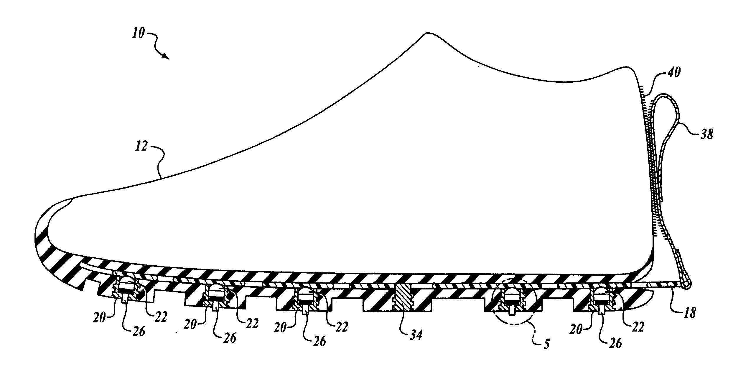
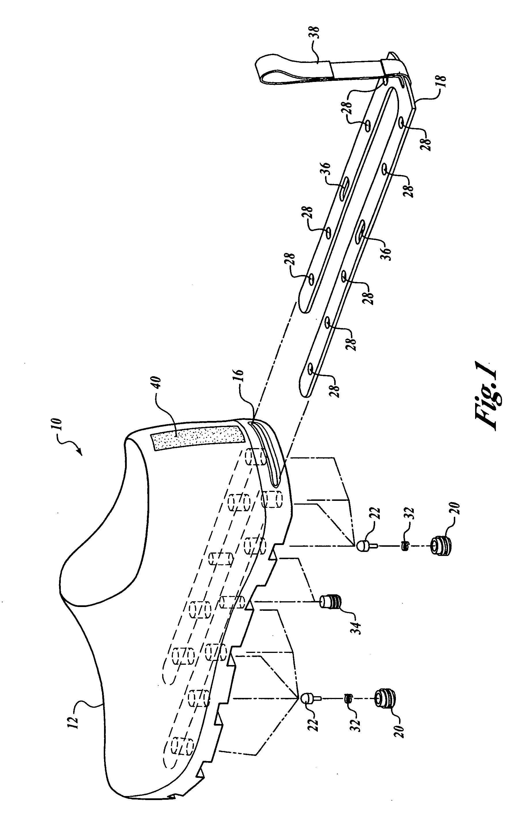
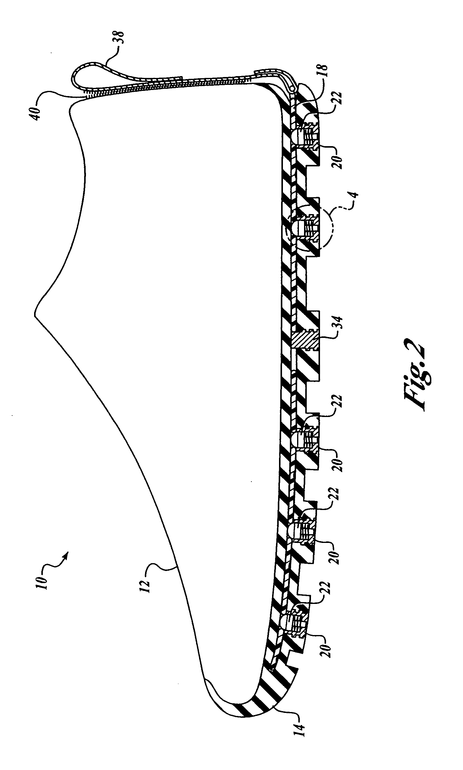
[0031] Referring to the figures, and especially FIGS. 1 through 4 initially, the present invention can be described. FIG. 1 shows an article of footwear 10 and for ease of description will be referred to as shoe 10. It is understood that the upper portion of the footwear can be in any well known configuration such as a conventional shoe, boot, athletic shoe, or any equivalent. The shoe 10 has an upper portion 12 with a lower portion or sole 14. Sole 14 runs the length of the shoe 10 on its bottom and has a narrow cavity 16 therein. Cavity 16 has a slide plate 18 fitted therein and the slide plate 18 is substantially U-shaped as best shown in FIGS. 2 and 4. Sole 14 also has a plurality of treads 20 fitted therein, preferably threadably connected to the sole as shown in FIGS. 1 and 3. Treads 20 fit with sole 14 such that they are neither extended nor retracted relative to the sole 14 when the shoe 10 is in use, but actually form part of the walking surface of the shoe 10. Contained wi...


PUM


Abstract

Footwear having retractable studs that provide enhanced traction on slippery surfaces when engaged. A pull cord attached to a plate within the sole of the shoe allows the studs to engage. The working parts of the shoe can be easily taken apart for cleaning or de-icing. An alternative embodiment of the shoe has a mechanism similar to that of a conventional ball point pen which is used to effectively engage or retract the studs.

Description

BACKGROUND OF THE INVENTION [0001] 1. Field of the Invention [0002] This invention relates in general to footwear for use on slippery surfaces such as ice and snow, and more particularly to footwear having retractable studs that provide enhanced traction on slippery surfaces when engaged. [0003] 2. Description of the Prior Art [0004] In climates that experience ice and snow, especially during the winter season, many accidents occur when an unsuspecting person falls on an icy sidewalk or street resulting in injury due to an unrecognized danger. For example, in many cities a sidewalk may be bare and wet in places, but still have icy patches in the same block which are hazardous to pedestrians. Falls on icy sidewalks or streets can result in serious injury and even death. These injuries tend to occur with more frequency to middle-aged and older people. To address this situation, there are many well-known prior art devices, ranging from overshoes with enhanced traction to special inclem...

Claims


Application Information

Patent Timeline
Patent Type & Authority Applications(United States)
IPC IPC(8): A43C15/00
CPCA43C15/14
Inventor JONES, PETER C.
Owner JONES PETER C
Why Eureka
Try Eureka