Auger assembly

a technology of augers and shafts, which is applied in the direction of fishing, drilling pipes, light and heating equipment, etc., can solve the problems of heavy and environmental damage, heavy weight, and inability to remove the tubes with helical flights from the shafts,

Active Publication Date: 2011-05-24
A W C CORP
View PDF25 Cites 37 Cited by
  • Summary
  • Abstract
  • Description
  • Claims
  • Application Information

AI Technical Summary

Benefits of technology

[0004]The auger assembly of the invention has a plurality of flight units supported on a shaft adapted to be rotated whereby fluid-like materials are moved by the flight units to selected locations. Adjacent flight units have cooperating members, such as lugs and recesses, drivably connecting the flight units. The flight units are separately removed whereby broken flight units can be removed and replaced with new flight units. The flight units have helical-shaped flights located in staggering relationship or linear relationship along the length of the shaft whereby the flights when rotated efficiently move the fluid-like materials.

Problems solved by technology

Metal augers driven with internal combustion engines are bulky, heavy and environmentally detrimental.
The tubes with helical flights are not removable from the shafts to allow a person to repair broken augers and helical flights by replacing the broker augers and related parts.

Method used


Image

  • Auger assembly
  • Auger assembly
  • Auger assembly

Examples


Embodiment Construction

[0024]In the following detailed description of the auger assembly and ice drill of the invention, reference is made to the accompanying drawing that from a part hereof, and in which are shown, by way of illustration, specific embodiments in which the invention may be practiced. It is to be understood that other embodiments may be utilized and structural changes may be made without departing from the scope of the present invention.

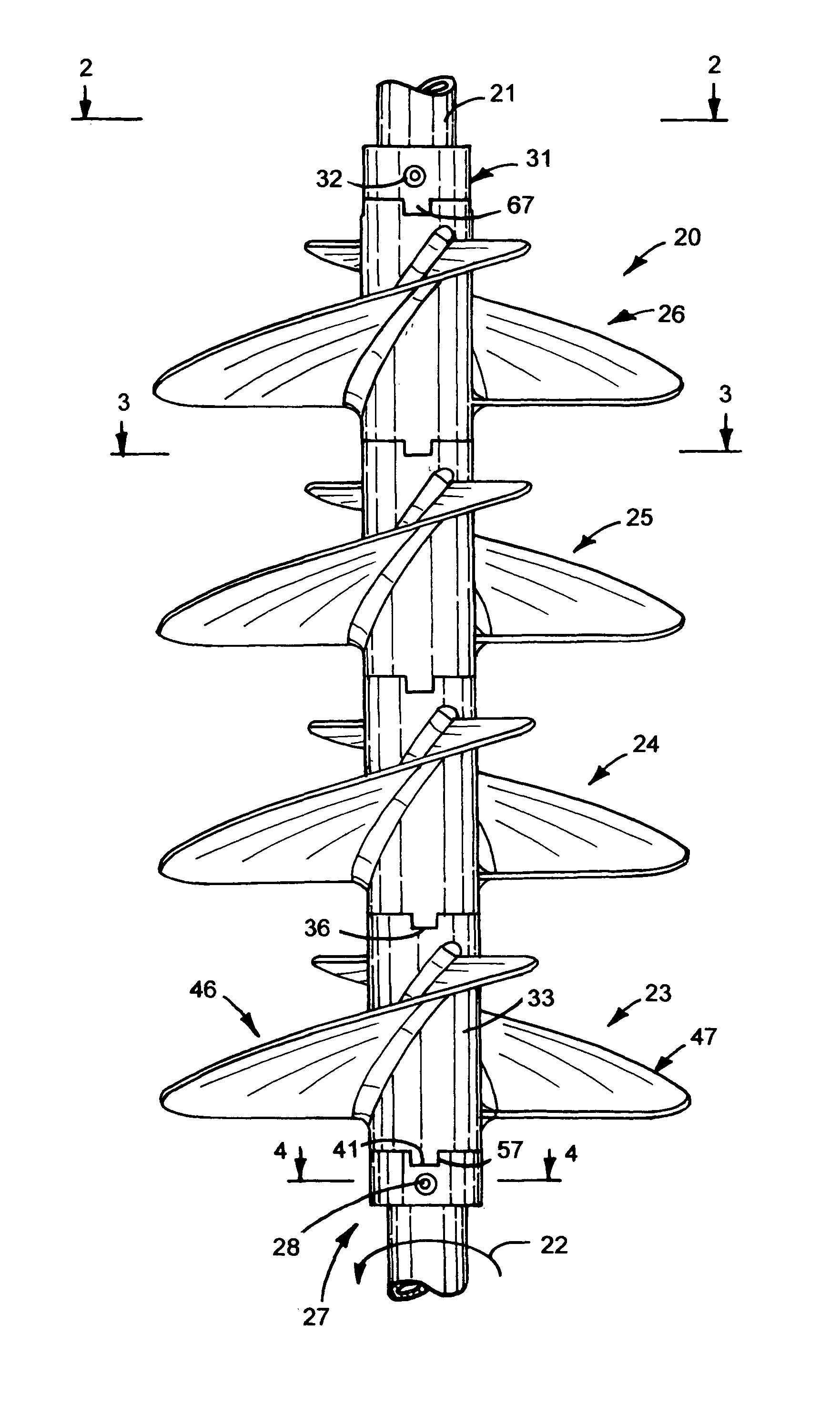
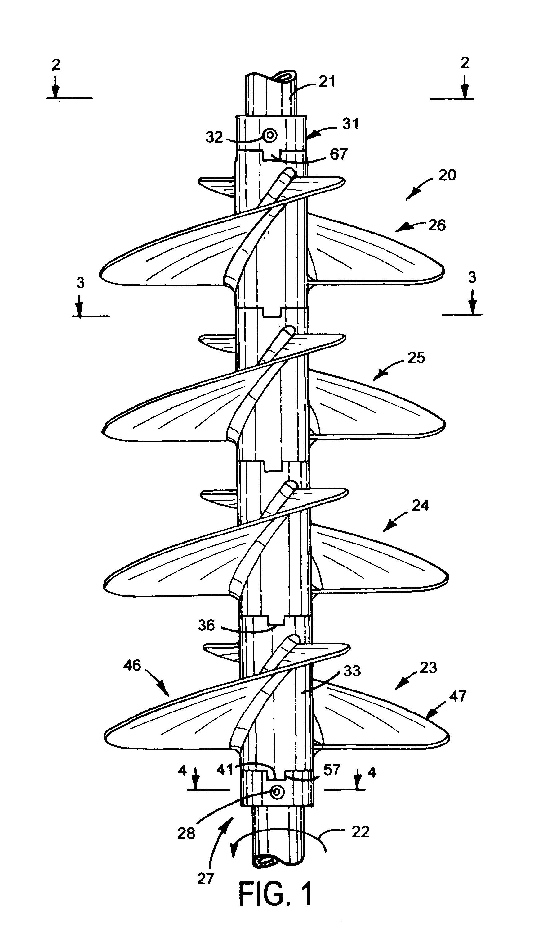
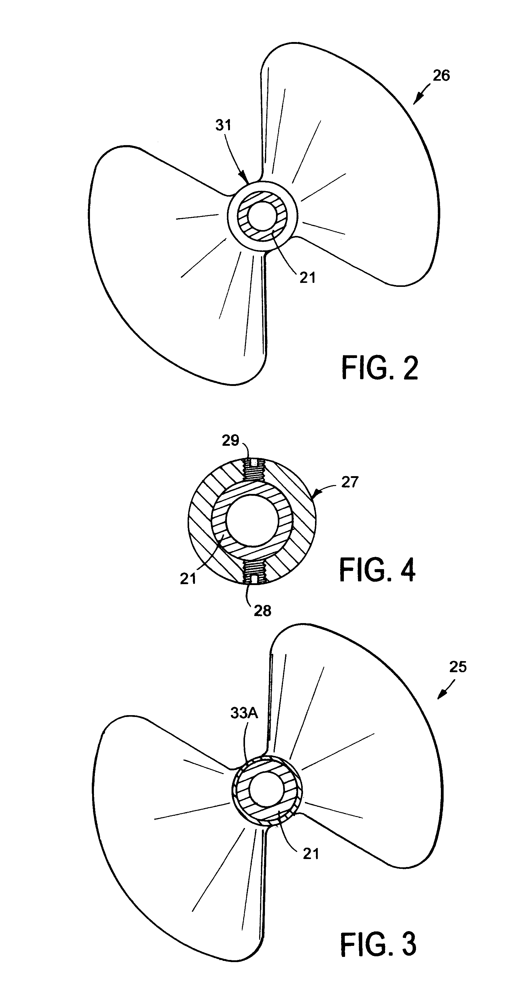
[0025]One embodiment of the invention, shown in FIGS. 1 to 4, is an auger assembly 20 having a drive shaft 21 adapted to be rotated about its longitudinal axis as indicated by arrow 22. Auger assembly 20 is used in conveyors to transport particulate materials, grain, fibers, liquids, gases, snow and ice particles. Shaft 21 is a linear tubular metal member adapted to be connected to a powered device, such as a motor or power transmission apparatus. Shaft 21 can be a linear solid cylindrical member including a plastic tube. A plurality of flight units 23, 24,...


PUM


Abstract

An auger assembly has a shaft supporting flight units having lug and recess connections allowing broken flight units to be removed from the shaft and replaced with another flight unit. The auger assembly is incorporated in an ice drill having a cordless electric motor and a cutting head. A coupling locks the auger assembly on the motor drive shaft.

Description

CROSS REFERENCE TO RELATED APPLICATION[0001]This application is a continuation of and claims the priority of U.S. Provisional Application Ser. No. 60 / 879,299 filed Jan. 8, 2007.FIELD OF THE INVENTION[0002]The invention relates to rotatable auger assemblies used to move fluid-like materials to selected locations.BACKGROUND OF THE INVENTION[0003]Auger assemblies are used to transport and convey fluid-like materials, including but not limited to particulate materials, grains, fibers, water, snow and ice particles to desired locations. Conventional auger assemblies have elongated linear shafts with continuous helical flights fixed to the shafts. Power transmissions and motors connected to the shafts operate to rotate the auger assemblies to move the materials along the helical flights. Augers with cutting heads used with hand cranks and internal combustion motors to drill holes in ice on lakes and rivers for ice fishing. These augers have metal construction with high cutting torque that...

Claims


Application Information

Patent Timeline
Patent Type & Authority Patents(United States)
IPC IPC(8): F25C5/04E21B10/44
CPCA01K97/01F25C5/04E21B10/44E21B7/008
Inventor KLUGE, DOUGLAS J.
Owner A W C CORP
Why Eureka
Try Eureka