Fastening element

a technology of fastening elements and components, applied in the direction of fastening means, securing devices, screws, etc., can solve the problems of reducing the strength of polar thermoplasts, reducing the risk of material chunking around the set fastening element in the region of the borehole mouth, and preventing deformation of polar thermoplasts

Inactive Publication Date: 2011-05-31
RESTALYST PTE +1
View PDF34 Cites 30 Cited by
  • Summary
  • Abstract
  • Description
  • Claims
  • Application Information

AI Technical Summary

Benefits of technology

[0009]Upon the fastening element being screwed in, the coating heats up, whereby a limited, radially outer region, which would be further referred to as a melting region, becomes heated to a melting temperature of the polar thermoplast, which is favorable to an easy bonding of the coating with the wall of the borehole. Thereby, with the layer thickness adapted to the dimensions of the fastening element and the borehole, a complete sealing of the borehole against fluid media is ensured. The bonding of the coating with the wall of the borehole has little adhesive effect, so that a set fastening element can be removed later in a simple manner, without destroying the region of the constructional component that surrounds the fastening element. The borehole tolerances are directly compensated during the setting process. Further, the inventive fastening element has, in its setting condition, noticeably greater anchoring characteristic values in comparison with a non-coated fastening element and, thus, a greater bearing capacity. Simultaneously, the inventive fastening element ensures ruggedness of the setting process.
[0024]After the inventive fastening element has been set and the melting region of the coating has been cooled, the deformation of the polar thermoplast is practically prevented in all of the spatial directions. Thus, the small strength of the polar thermoplast does not adversely affect the produced attachment. When a force is applied to the polar thermoplast it reacts quasi hydrostatically and contributes to the transfer of load, which is applied to the fastening element, into the constructional component. Thereby, high anchoring characteristic values are realized.

Problems solved by technology

The drawback of the proposes solution consists in that for setting a fastening element with an elastomeric coating high screw-in torques are necessary which exceed power limits of a number of screw-driving power tools or even the torsional strength of a fastening element.
Further, the deformation of the elastomeric coating leads to generation of expanding forces in the gap which can lead, in particular in the region of the borehole mouth and at small edge and axial distances of the fastening elements, to spalling on the surface of the constructional component.

Method used


Image

  • Fastening element
  • Fastening element

Examples


Embodiment Construction

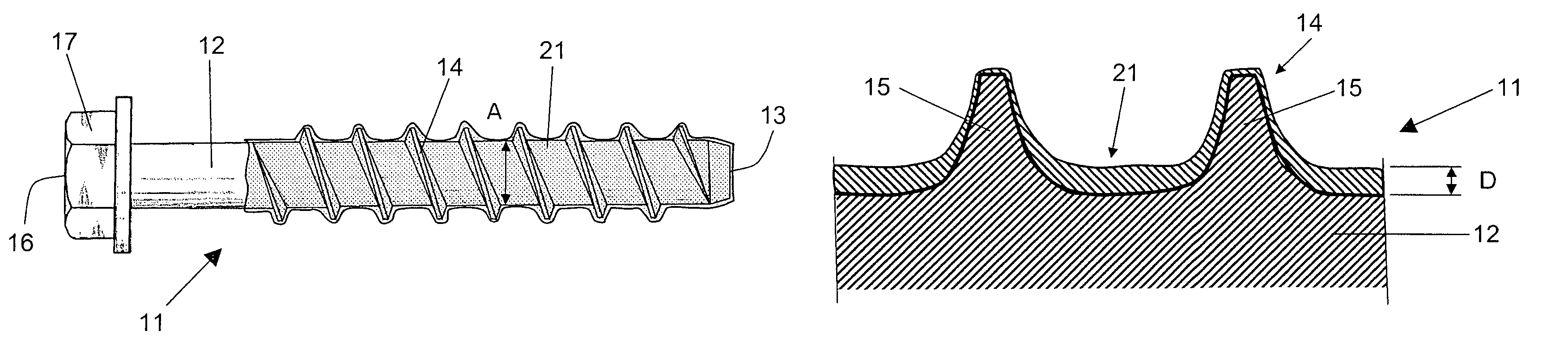
[0031]A fastening element 11 according to the present invention for a mineral constructional component 6, which is shown in FIG. 1, is formed as a self-tapping screw having a shaft 12 with a first, setting side end 13 and a second end 16 opposite or remote from the first end 13. At the second end 16, there is provided rotatable application means 17 in form of a hegonal screw head for a setting tool, not shown here. Starting from the first end 13 of the shaft 12, a thread-tapping thread 14 extends regionwise along the shaft 12. From the first end 13 in the direction of the second end 16, regionwise, the shaft 12 is provided with a coating 21 from a polar thermoplast. As a polar thermoplast, ethylenvinylacetate (EVA) is used that has a melting temperature according to DSC of 60° C. and a strength of 4 N / mm2. The polar thermoplast is applied on the fastening element 11, at least in the region of the thread 14 by a whirl sintering process.

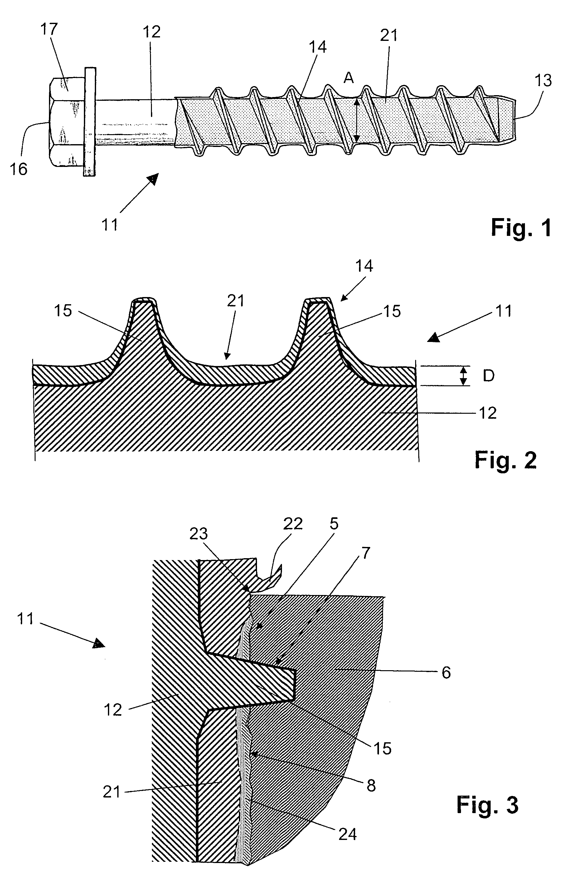
[0032]As shown in FIG. 2, the coating 21 has a b...


PUM


Abstract

A fastening element for mineral constructional components has a shaft (12) provided with a tapping thread (14) extending, at least regionwise, along the shaft (12), and a coating (21) that covers the shaft (12) likewise at least regionwise and that is formed of a polar thermoplast.

Description

BACKGROUND OF THE INVENTION[0001]1. Field of the Invention[0002]The present invention relates to a fastening element for mineral constructional components and including a shaft having rotatable application means, a tapping thread extending, at least regionwise, along the shaft, and a coating provided on the shaft, at least regionwise.[0003]2. Description of the Prior Art[0004]German Publication DE 102 43 537 A1 discloses a fastening element for mineral constructional components and having a shaft. At one end of the shaft, there is provided, e.g., a hexagonal head as a rotatable application means, for a setting tool, and a tapping thread that extends, starting from the shaft end opposite the rotatable application means, along the shaft at least regionwise. The shaft is provided, regionwise, with a coating of eleastomeric material. The strength of the coating is so selected that upon screwing of the fastening element in, it becomes partially compressed sealing the intermediate space b...

Claims


Application Information

Patent Timeline
Patent Type & Authority Patents(United States)
IPC IPC(8): F16B1/00
CPCF16B25/0026F16B33/004F16B39/225F16B33/06Y10S411/914
Inventor ROSENKRANZ, FALK
Owner RESTALYST PTE
Why Eureka
Try Eureka