Method and apparatus for reducing speckle in coherent light

a coherent light and liquid crystal film technology, applied in the field of display systems, can solve the problems of face constraints associated with providing such increased resolution and brightness, and produce images with noticeable granularity, so as to reduce spatial coherence and reduce speckle in images produced

Active Publication Date: 2011-06-07
TEXAS INSTR INC
View PDF8 Cites 8 Cited by
  • Summary
  • Abstract
  • Description
  • Claims
  • Application Information

AI Technical Summary

Benefits of technology

According to one embodiment, a method for reducing speckle in an image produced from a coherent light source includes directing a beam of coherent light at an electrically controlled diffuser. An electrical signal is applied to the electrically controlled diffuser to produce an electrical field across the electrically controlled diffuser layer. At least one of an amplitude and a frequency of the electrical signal are varied to transition the controlled diffuser between a first state and a second state. The varied application of the electrical signal operates to reduce spatial coherence in an image projected through the electrically controlled diffuser.
Some embodiments of the invention provide numerous technical advantages. Some embodiments may benefit from some, none, or all of these advantages. For example, according to one embodiment, fewer moving parts are used for speckle reduction. As a result, system components are subject to less wear and tear. Additionally, product assembly may be made easier as compared to motion-based systems that required a motor and adequate spacing to accommodate moving components. The reduction in spacing between optical elements may help improve the form factor of the projector.
Still another advantage may be that, because low drive voltages are required to manipulate the molecular structure of the electrically controlled diffuser 104, the described system consumes less power than prior motion-based systems. Further, the lack of moving parts may improve user satisfaction since the amount of noise associated with working components may be reduced
Still another advantage may be that in a rear projection system the Fresnel lens may be made thinner and more compact. Specifically, since the Fresnel lens is not moving, it is less susceptible to bowing. Accordingly, it may be made thinner. Further, since no separation is needed between the Fresnel lens and the lenticular to separate moving parts, the cabinet in which the imaging system is housed may be made smaller.

Problems solved by technology

Engineers continue to try to increase the resolution and brightness of imaging systems to provide better picture quality, but also face constraints associated with providing such increased resolution and brightness.
However, while coherent light sources may increase the brightness of the display system, such light sources often produce images having a noticeable granularity.

Method used


Image

  • Method and apparatus for reducing speckle in coherent light
  • Method and apparatus for reducing speckle in coherent light
  • Method and apparatus for reducing speckle in coherent light

Examples


Embodiment Construction

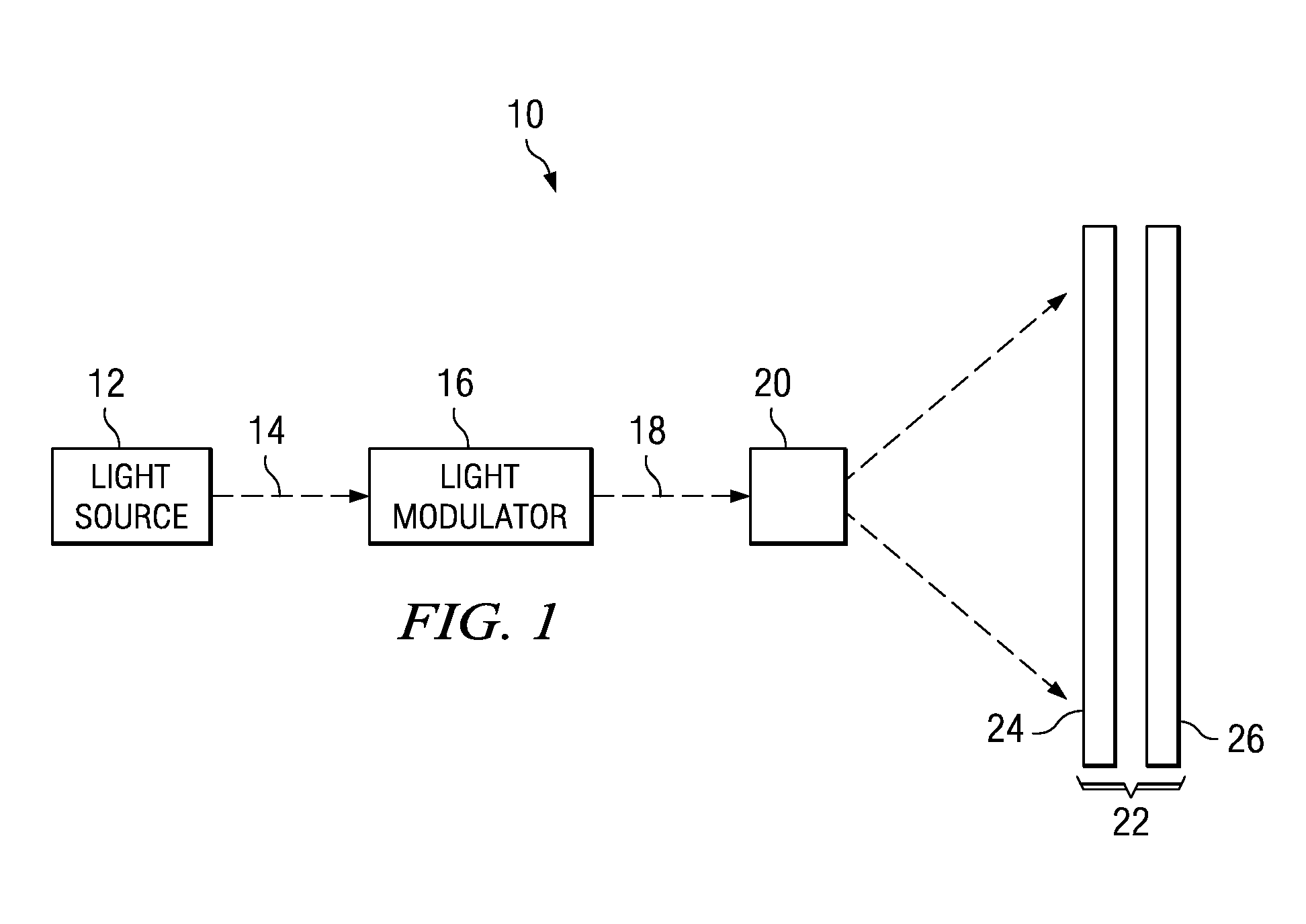
Embodiments of the invention and its advantages are best understood by referring to FIGS. 1-4 of the drawings, like numerals being used for like and corresponding parts of the various drawings.

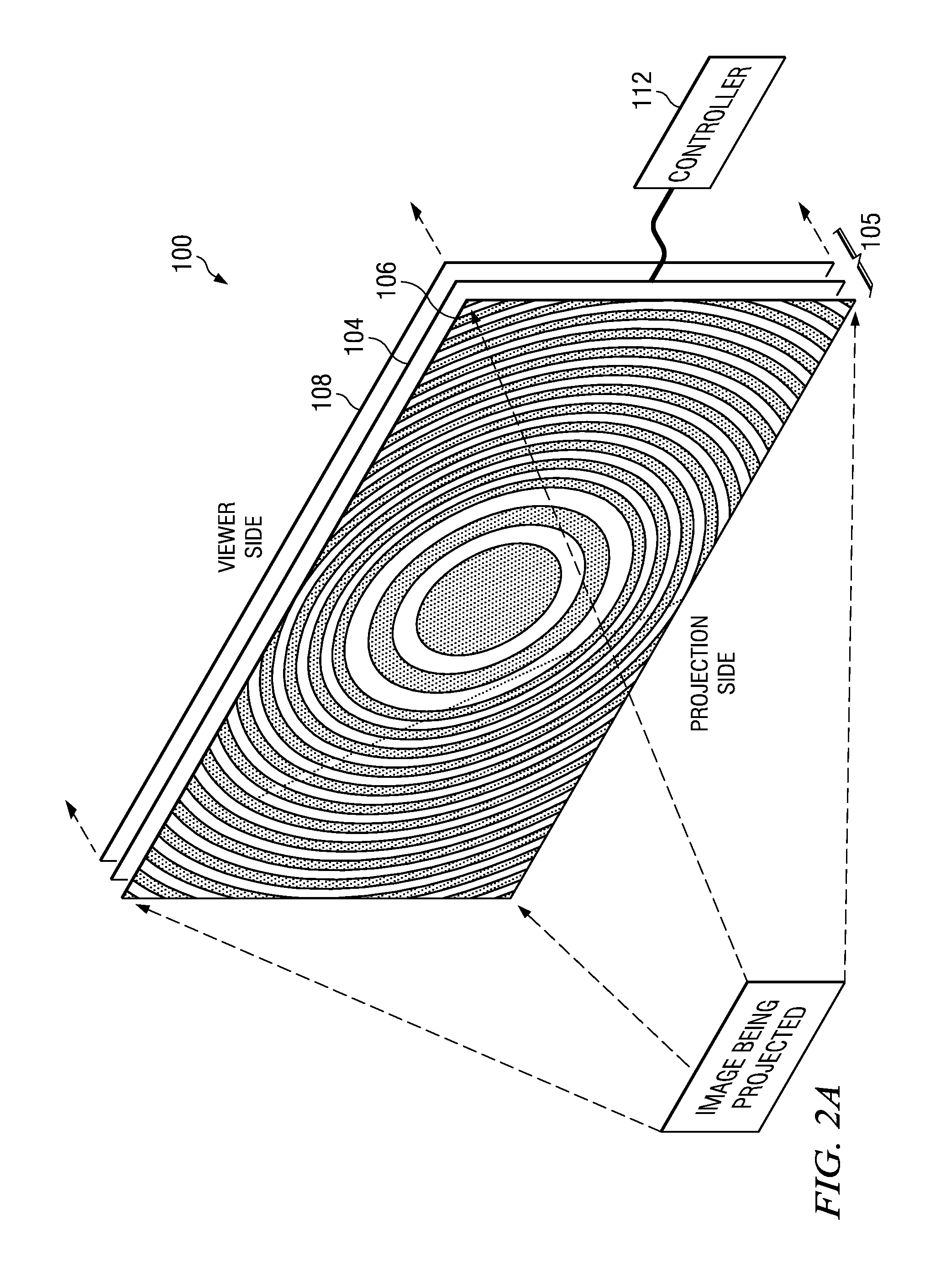
When a visible coherent light beam, such as that from a laser, for example, illuminates a fixed diffuse reflecting surface such as a matte white screen, the illuminated area has a sparkling appearance. The same observation can be made when such a coherent light beam is directed onto a stationary diffuse optical transmission surface such as a rear projection display screen. The sparkling appearance results in images having a noticeable granularity. This grainy pattern is also referred to as speckle or the scintillation effect.

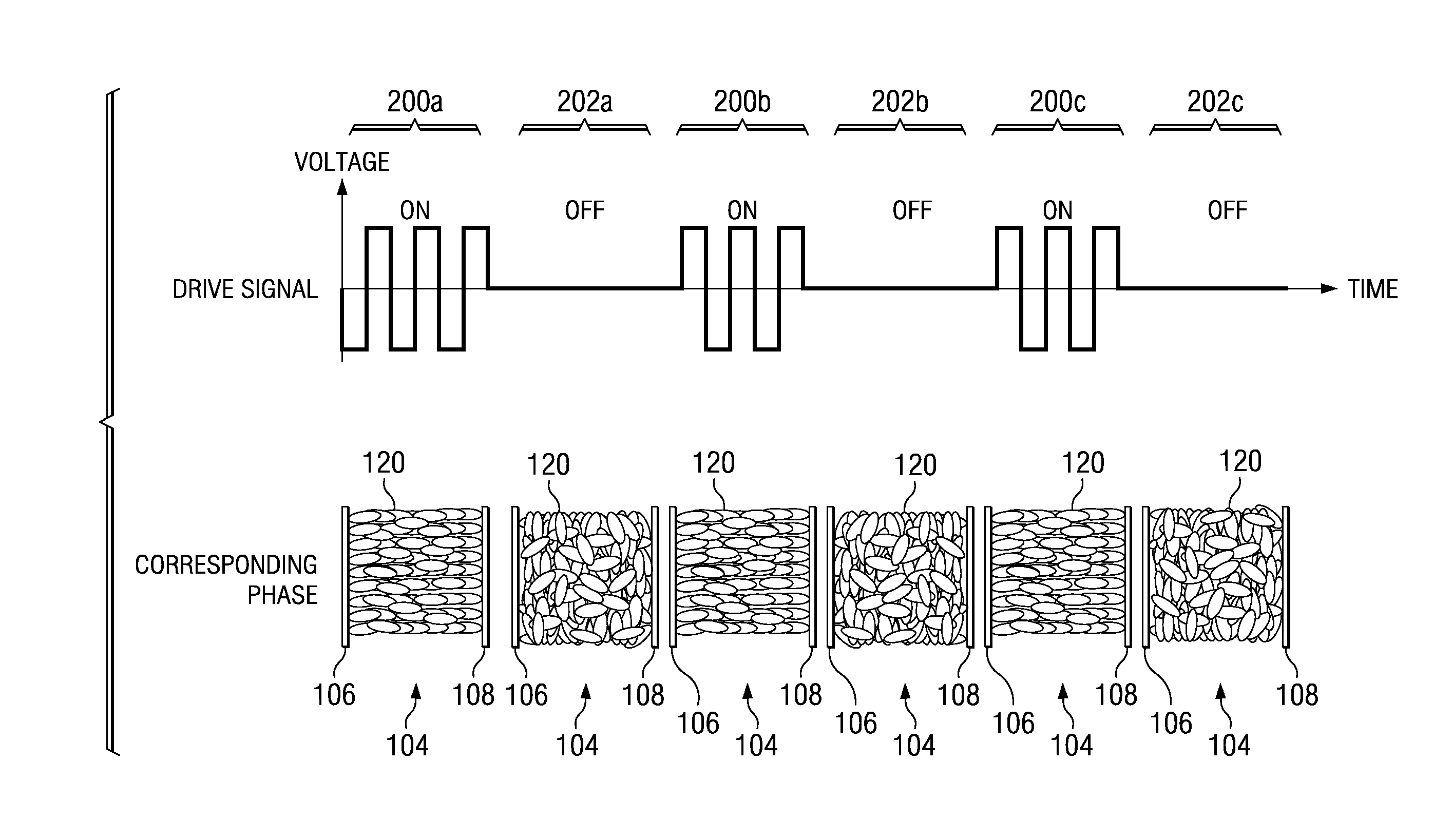
One approach to diminish the visibility of speckle utilizes motion to break up the stationary diffraction pattern caused by coherent light. In such a system, one or more elements of the imaging system that have diffusion properties are continually vibrated, rotated, or mov...


PUM

PropertyMeasurementUnit
full width half maximum diffusion angleaaaaaaaaaa
diffusion angleaaaaaaaaaa

Abstract

According to one embodiment, a method for reducing speckle in an image produced from a coherent light source includes directing a beam of coherent light at an electrically controlled diffuser. An electrical signal is applied to the electrically controlled diffuser to produce an electrical field across the electrically controlled diffuser layer. At least one of an amplitude and a frequency of the electrical signal are varied to transition the controlled diffuser between a first state and a second state. The varied application of the electrical signal operates to reduce spatial coherence in an image projected through the electrically controlled diffuser.

Description

TECHNICAL FIELD OF THE INVENTIONThis invention relates generally to display systems and more particularly to a method and apparatus using liquid crystal films to reduce speckle in coherent light.BACKGROUND OF THE INVENTIONTelevisions and other types of imaging systems are pervasive in today's society. Recent years have seen the introduction of higher definition imaging systems. Engineers continue to try to increase the resolution and brightness of imaging systems to provide better picture quality, but also face constraints associated with providing such increased resolution and brightness.For example, to increase brightness in imaging display systems, coherent light sources such as lasers may be used in the place of incoherent light sources such as light-emitting-diodes (LEDs) and lamps. However, while coherent light sources may increase the brightness of the display system, such light sources often produce images having a noticeable granularity. This grainy pattern, also known as s...

Claims


Application Information

Patent Timeline
Patent Type & Authority Patents(United States)
IPC IPC(8): G02F1/133G02F1/1333G09G3/36
CPCG02B27/48H04N9/3161H04N9/3129
Inventor KHAN, SAJJAD ALI
Owner TEXAS INSTR INC
Why Eureka
Try Eureka