Rear projection screen with reduced speckle

a rear projection screen and speckle technology, applied in projectors, optics, instruments, etc., can solve the problems of limited resolution, disturbing artifacts in the form of speckle patterns, and limit the ultimate resolution of the screen, so as to reduce the speckle pattern of the rear projection screen

Inactive Publication Date: 2001-12-04
PHILIPS ELECTRONICS NORTH AMERICA
View PDF4 Cites 32 Cited by
  • Summary
  • Abstract
  • Description
  • Claims
  • Application Information

AI Technical Summary

Benefits of technology

Accordingly, it is a principal object of the invention to reduce the speckle pattern in rear projection screens.
It is another object of the invention to reduce the speckle pattern in rear projection screens, while maintaining the resolution, viewing space and gain of the screen.
It is another object of the invention to modify the existing TIR-type rear projection screens to reduce the speckle pattern without destroying the resolution or significantly changing the viewing space or gain of the screen.
Further in accordance with the invention, we have recognized that the speckle in rear projection screens of the type having a front lenticular surface can be substantially reduced by incorporating a diffraction grating into the rear surface of the screen.
Use of such a diffraction grating to modify the existing TIR-type rear projection screens significantly reduces the speckle pattern without destroying the resolution or significantly changing the viewing space or gain of the screen.

Problems solved by technology

This limits the minimum pitch (distance between the lenticules) to about 0.5 mm, which in turn limits the ultimate resolution of the screen.
Since there is no relationship between the thickness of the screen and the pitch of the lenticules, resolution is limited only by the ability to manufacture the individual lenticular elements.
When these screens are used with high magnification systems in which the projection beam is nearly coherent, a disturbing artifact in the form of a speckle pattern is often observed.
We have observed that increasing the amount of diffusion and increasing the thickness of the diffuser also can reduce the visibility of the speckle, but on the other hand deteriorates the resolution o f the screen.

Method used


Image

  • Rear projection screen with reduced speckle
  • Rear projection screen with reduced speckle
  • Rear projection screen with reduced speckle

Examples


Embodiment Construction

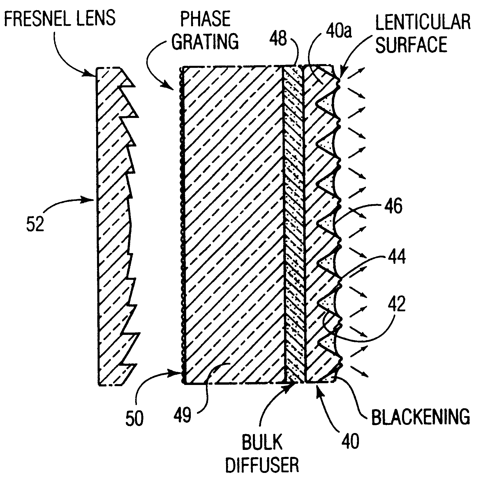
FIG. 4 shows the preferred embodiment of this invention, a rear projection screen having a front piece or substrate with a front lenticular lens array 40, a bulk diffusing region 48 and a rear surface defining a diffraction grating 50. The front surface is defined by individual mutually parallel lenticular elements or lenticules 40a, each having sidewalls 42 and tip regions 44. As shown, a linear phase grating 50, sometimes referred to as a micro-lenticular or micro lens array, and a bulk diffuser 48 are separated by a clear region 49. The bulk diffuser 48 may also extend into the lenticular region 40 as far as the tip region. The thickness of the clear region or non-diffusing region 49 is typically about 3 mm.

FIG. 9 shows an enlarged portion of the phase grating 50, in which the individual mutually parallel gratings 50a have a cylindrical surface 52, defined by a radius r and a pitch a. The thickness of the substrate and the grating parameters are designed to provide just enough sp...


PUM


Abstract

A rear projection screen which includes a front lenticular surface, a diffusion region behind the lenticular surface, a non-diffusion region behind the diffusion region, and a rear phase grating surface, when used with high magnification projection systems, exhibits reduced speckle when compared to other rear projection screen without such a grating.

Description

BACKGROUND OF THE INVENTIONThis invention relates to rear projection screens, and more particularly relates to such screens for use projectors in which the projection beam is nearly coherent.Rear projection screens transmit to an audience space an image projected onto the rear of the screen. The performance of rear projection screens is characterized by their gain (defined as the luminance of the screen in the forward going direction with respect to the luminance from an ideal lambertian reflector), their viewing space, resolution, contrast and artifacts. An ideal rear projection screen would provide a clear crisp, high contrast, bright image for a large audience space. That is, the screen would have 1) high resolution, 2) freedom from artifacts, 3) contrast enhancement, 4) high gain and 5) spreading of the light from the projector into a large range of vertical and horizontal angles.In reality, a screen that exhibits all these characteristics does not exist. For instance, to increa...

Claims


Application Information

Patent Timeline
Patent Type & Authority Patents(United States)
IPC IPC(8): G03B21/62
CPCG03B21/625G03B21/62G03B33/14
Inventor GOLDENBERG, JILL F.HUANG, QIANGVAN DE VEN, JOHANNES C.
Owner PHILIPS ELECTRONICS NORTH AMERICA
Why Eureka
Try Eureka