Line illumination apparatus using laser arrays

a laser array and illumination apparatus technology, applied in the field of illumination apparatus, can solve the problems of high cost of increasing output power, unsuitable for use with gems or glv light modulators in display applications, and unsuitable for high-coherent laser solutions, etc., and achieve the effect of reducing speckles

Inactive Publication Date: 2010-07-08
EASTMAN KODAK CO
View PDF25 Cites 31 Cited by
  • Summary
  • Abstract
  • Description
  • Claims
  • Application Information

AI Technical Summary

Benefits of technology

[0025]It is an advantage of the present invention that it provides a thin linear illumination that exhibits single-mode characteristics in the width dimension. It is a further advantage of the present invention that it provides a way to combine laser array sources with reduced speckle. Unlike earlier illumination approaches using laser arrays, the apparatus and methods of the present invention can compensate for or eliminate visible coherence artifacts and speckle that result from correlation of corresponding forward- and backward-propagating elements of laser arrays in various configurations.
[0026]These and other aspects, objects, features and advantages of the present invention will be more clearly understood and appreciated from a review of the following detailed description of the preferred embodiments and appended claims, and by reference to the accompanying drawings.

Problems solved by technology

This means preserving, as closely as possible, the original power distribution profile of the light that is emitted from the laser array itself This is a difficult task, made more arduous as the light is processed by each successive optical component.
Conventional solutions for providing linear illumination for GEMS devices have not taken advantage of laser arrays, but have employed single-mode, single-beam lasers for this purpose, with disappointing results.
For example, maintaining the desired uniformity (ii) for a line of illumination of sufficient length proves to be a challenge when using single-beam lasers.
Providing single-mode illumination (iii) is a challenge that is generally not recognized as a requirement with existing illumination systems.
A disadvantage of single-beam lasers relates to power scaling; an incremental increase in output power can be disproportionately high in cost.
However, with this type of solution, the laser light from the array of sources is not provided as a thin line of light, but must be spread over a broad area, uniformly diffused over the full surface of the two-dimensional micromirror-based array.
Although this type of solution provides a line of light from a laser array, the characteristics of the light provided are not suitable for use with GEMS or GLV light modulators in display applications.
This solution is not suitable for highly coherent lasers.
The Moulin '631 solution is constrained in terms of power output capability, limited to the output power that is available from a single laser array.
Designed for printhead functions in the infrared spectrum, the Moulin solution would not be usable with GEMS- or GLV-based writers, display projectors, or other apparatus for example.
However, the solution of the Gelbart '359 disclosure does not satisfy the line width requirements given in (i) above, nor address the need for single-mode light in the cross-array direction, reduced speckle, telecentricity of light, or the need for increased power using multiple arrays while preserving a suitable power distribution profile as in (iii)-(vi) above.

Method used


Image

  • Line illumination apparatus using laser arrays
  • Line illumination apparatus using laser arrays
  • Line illumination apparatus using laser arrays

Examples


Embodiment Construction

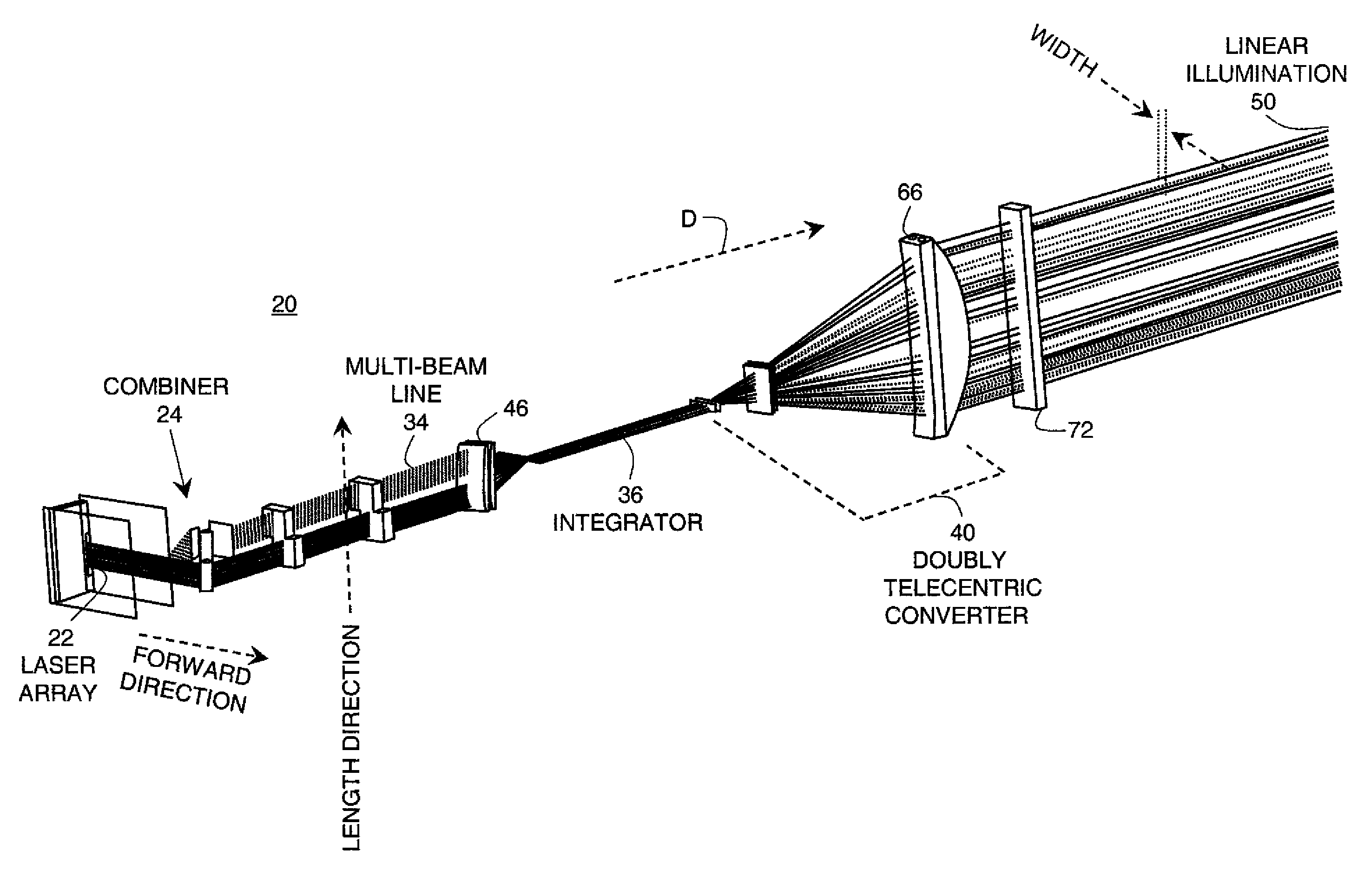
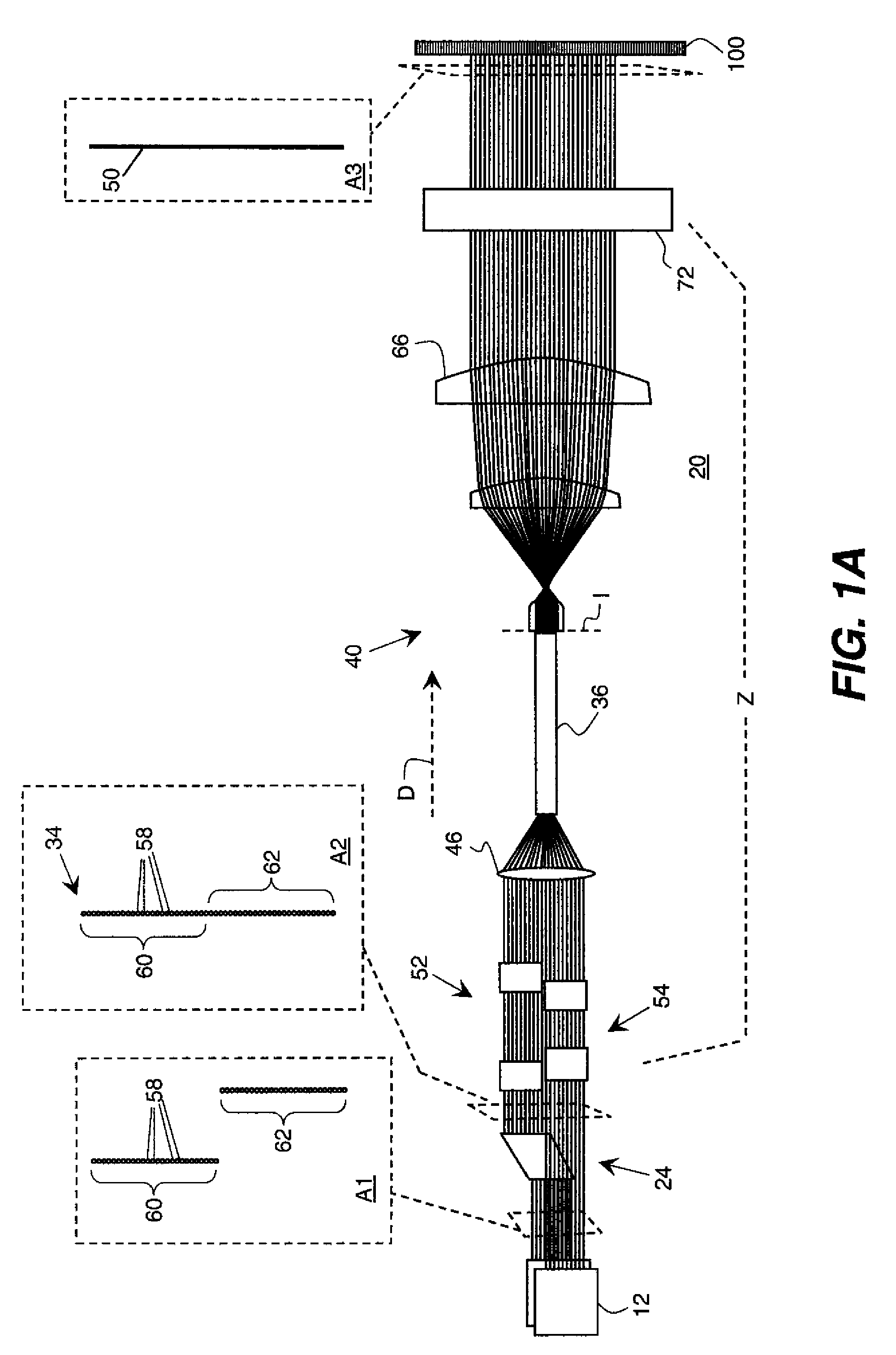
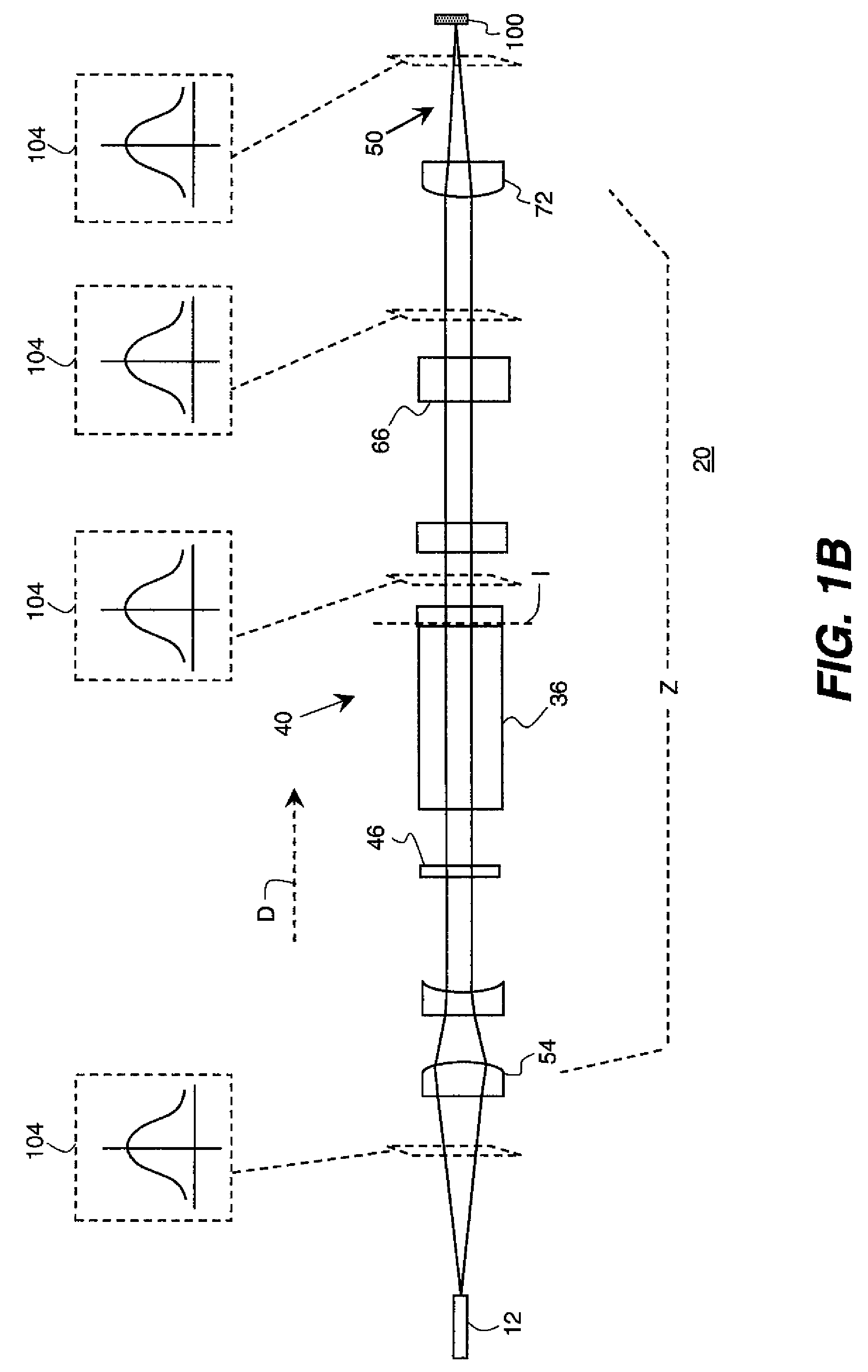
[0047]The present description is directed in particular to elements forming part of, or cooperating more directly with, apparatus in accordance with the invention. It is to be understood that elements not specifically shown or described may take various forms well known to those skilled in the art. Figures shown and described herein are provided in order to illustrate key principles of operation of the present invention and are not drawn with intent to show actual size or scale. Some exaggeration may be necessary in order to emphasize relative spatial relationships or principles of operation.

[0048]In the context of the present disclosure, the term “cross-array” is equivalent to the width direction of the line of illumination that is generated by the apparatus of the present invention. The term “cross array” is descriptive of the use of the illumination apparatus of the present invention when it directs a line of illumination onto a linear array light modulator, such as a GEMS device...


PUM


Abstract

An illumination apparatus forms, onto a linear array light modulator, a line of illumination that extends in a linear direction. The illumination apparatus has a first laser array with laser emitters for forming a first linear beam array and a second laser array with laser emitters for forming a second linear beam array. An array combiner aligns at least the first and second linear beam arrays in the linear direction and directs the first and second linear beam arrays along a propagation path to form a mixed illumination. At least first and second cylindrical lens elements having power in the linear direction relay the mixed illumination from the propagation path toward the linear array light modulator. At least third and fourth cylindrical lens elements having power in the cross-array direction that is orthogonal to the linear direction focus the mixed illumination onto the linear array light modulator.

Description

FIELD OF THE INVENTION[0001]This invention generally relates to illumination apparatus and more particularly to an apparatus for providing a line of light from two or more laser arrays.BACKGROUND OF THE INVENTION[0002]Laser arrays show particular promise as illumination sources in imaging applications where brightness, high efficiency, and long component life are needed. As the cost of solid-state laser sources continues to drop and the available spectral range expands, solid-state laser arrays have been proposed as possible sources for digital projection and display apparatus, providing advantages over other types of light sources.[0003]There are a number of applications for which a thin line of intense light is of particular interest. A number of spatial light modulators operate upon a single line of illumination and scan this line over a display surface for forming a two-dimensional image, for example. A general class of this type uses a linear array of micro-electromechanical mo...

Claims


Application Information

Patent Timeline
Patent Type & Authority Applications(United States)
IPC IPC(8): G02B27/10G03B21/14
CPCG02B27/0905G02B27/0966G03B21/28H04N9/3132G02B19/0057G02B19/0028G02B19/0014
Inventor KESSLER, DAVIDKOWARZ, MAREK W.PHALEN, JAMES G.AGOSTINELLI, JOHN A.MARCUS, MICHAEL A.
Owner EASTMAN KODAK CO
Why Eureka
Try Eureka