Methods and devices for determining position or distance

Inactive Publication Date: 2015-06-25
INTEL CORP
View PDF2 Cites 31 Cited by
  • Summary
  • Abstract
  • Description
  • Claims
  • Application Information

AI Technical Summary

Benefits of technology

[0045]The controller may be configured to decrease t

Problems solved by technology

In cases where the only the distance to the entity is of interest, the sensor uses unnecessary power

Method used


Image

  • Methods and devices for determining position or distance
  • Methods and devices for determining position or distance
  • Methods and devices for determining position or distance

Examples


Embodiment Construction

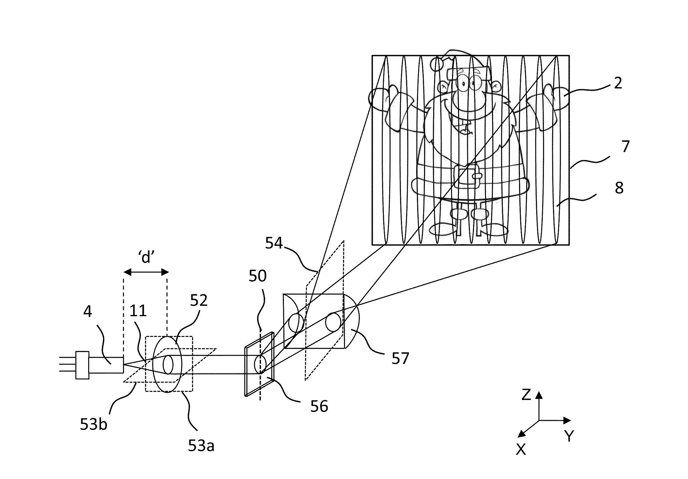
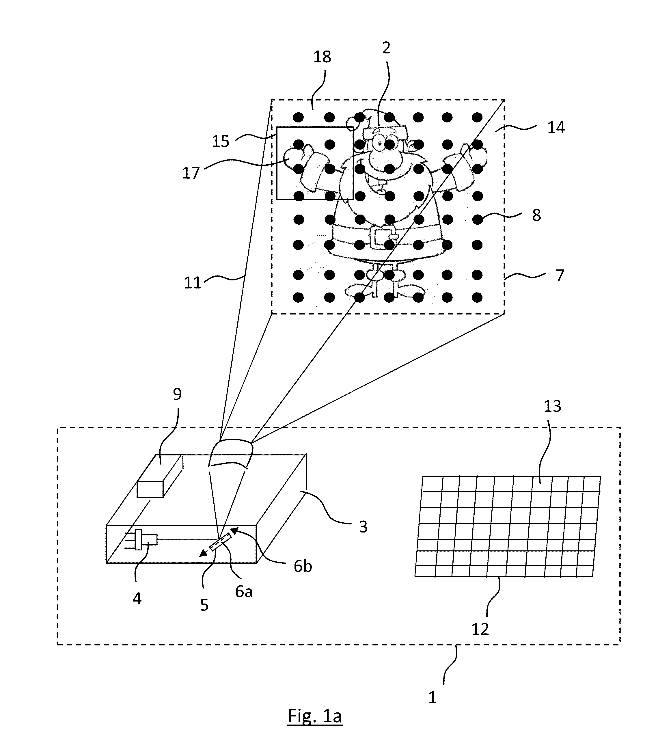
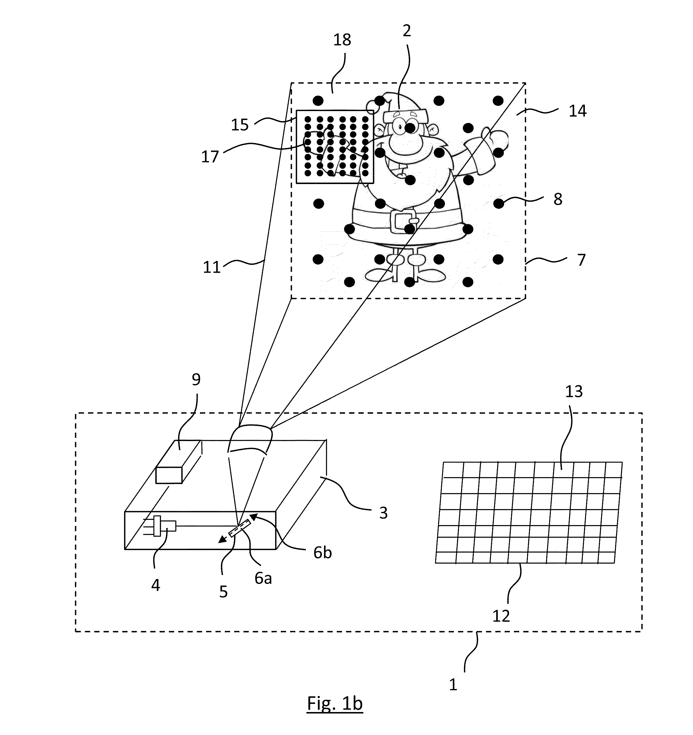
[0086]FIG. 1a,1b provide a perspective view of a device 1 for detecting the positioning of an entity 2, or the position or part of that entity 2, according to a first embodiment of the present invention.

[0087]The device 1 comprises, a projector 3, which comprises a laser 4 and a MEMS micro minor 5 arranged to receive light from the laser 4. It will be understood that any suitable light source may be used in place of a laser 4; preferably the laser 4 may be a VCSEL or laser diode or Resonant Cavity-LED or SLED. The light which is emitted from the laser 4 may be of a visible wavelength or may be Infra-Red light; in this example the laser 4 is configured to emit light which has a visible wavelength.

[0088]The MEMS micro minor 5 is configured such that it can oscillate about at least one oscillation axis 6a,b, to deflect light 11 towards the entity 2 so as to project an image 7, which is composed of pixels 8, onto the entity 2. In this example the MEMS micro minor 5 is configured such th...


PUM


Abstract

A method for detecting the positioning of an entity, comprising the steps of (a) using a projector, which comprises a laser and a MEMS micro mirror arranged to receive light from the laser and which can oscillate about at least one oscillation axis, to project light towards the entity to project an image which is composed of pixels onto the entity, wherein the image has a first density of pixels; (b) changing the density of pixels in the projected image; (c) sensing at least a portion of light of the projected image which is reflected from the entity; and (d) using the sensed portion of light to determine the position of the entity. There is also provided a corresponding device for detecting position. There is also provided a method and device for determining distance which involves using the sensed portion of light to determine the distance between the entity and projector.

Description

FIELD OF THE INVENTION[0001]The present invention concerns method and devices for detecting position or distance, and in particular to method and devices for detecting position or distance which involve changing the density of pixels in a projected image to provide for a more efficient position and / or distance measuring device and method.DESCRIPTION OF RELATED ART[0002]Distance measurement devices which comprise a light source which directs light to an entity and a sensor which senses light which has been reflected from that entity to determine the distance between the light source and entity, are known in the art. Typically the sensors of these distance measurement devices can determine the distance by determining the time of flight of the light or the phase of the light which it receives, or by triangulation using multiple cameras. Typically the light sources of these distance measurement devices are configured to emit infrared light or may emit visible light; the light sources ar...

Claims


Application Information

Patent Timeline
IPC IPC(8): G01B11/14A61B3/00G02B26/08
CPCG01B11/14A61B3/0016G02B26/0833G01B11/2513G03B21/26G01S17/08G01S17/50G01S7/4811G02B3/005G02B27/48G06F3/042
Inventor ABELE, NICOLASMASSON, JONATHANKILCHER, LUCIO
Owner INTEL CORP
Why Eureka
Try Eureka