
Method and system for manufacture and delivery of an emulsion explosive
- Summary
- Abstract
- Description
- Claims
- Application Information
AI Technical Summary
Benefits of technology
Problems solved by technology
Method used
Image

Examples
example one
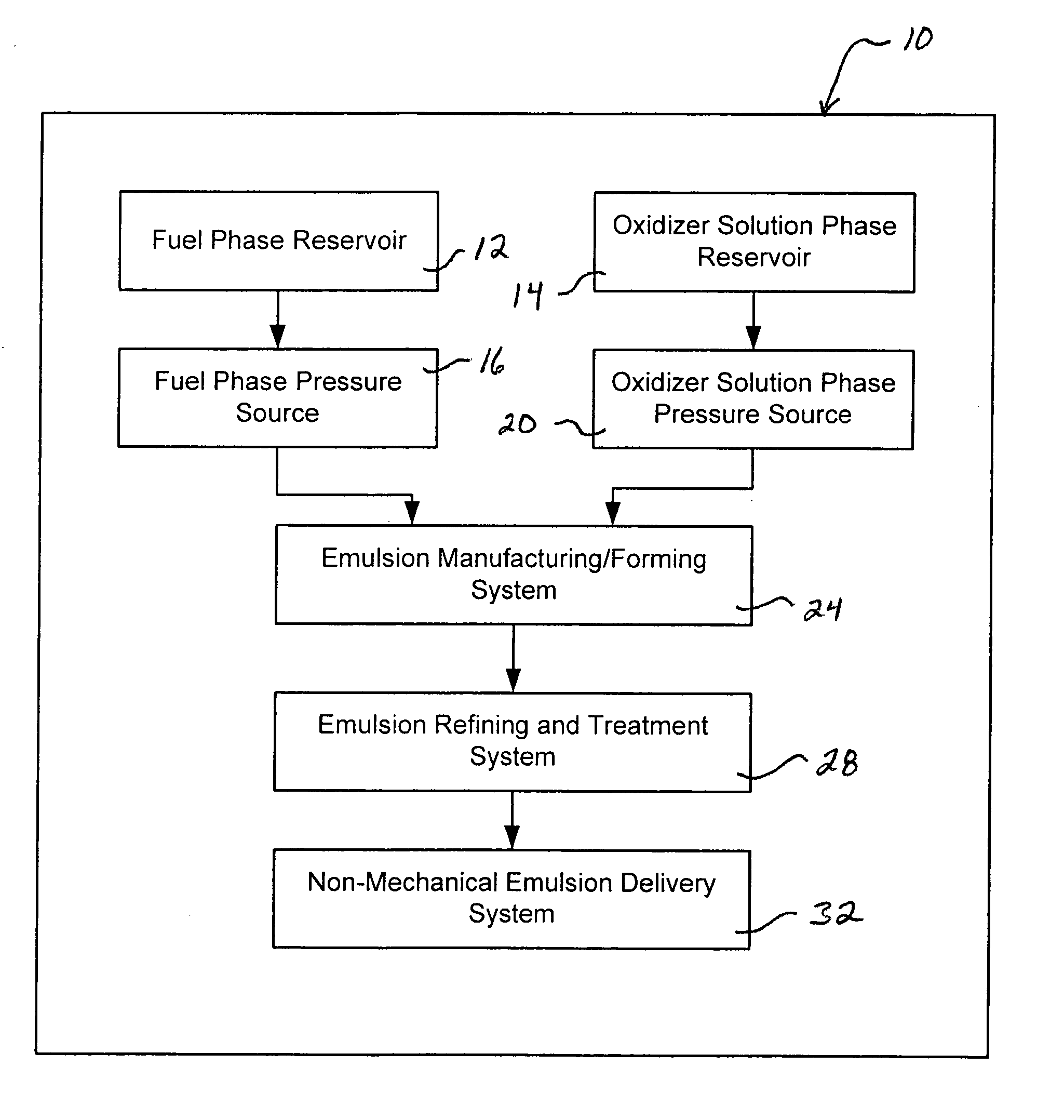
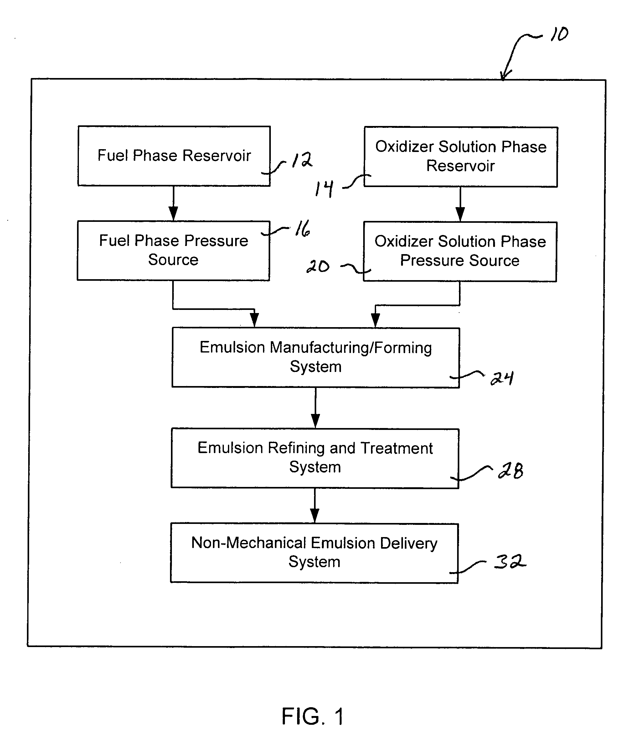
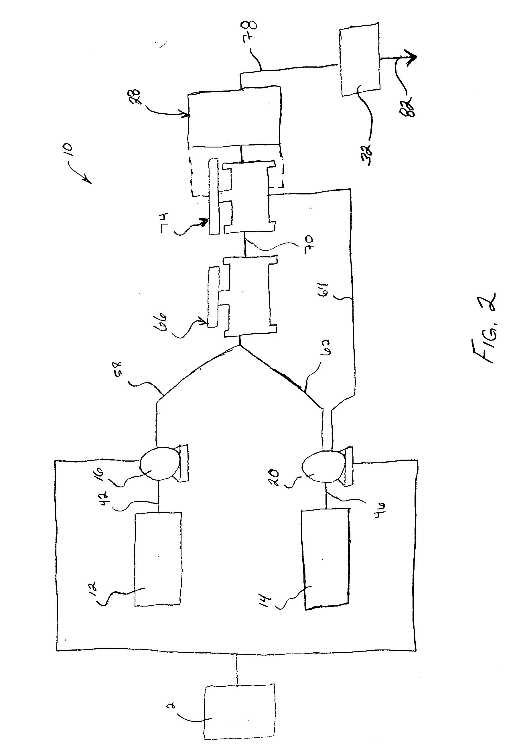
[0069] An emulsion explosive composition was formed at 500 pounds per minute (500 lbs. / min.). Fuel phase, with an emulsifier, was pumped through a first nozzle at a 30 pounds per minute (30 lbs. / min.) flow rate. A portion of oxidizer solution phase was pumped by a Waukesha oxidizer solution pump through a second nozzle at a 235 pounds per minute (235 lbs. / min.) flow rate. The oxidizer solution phase was split to more rapidly and efficiently form the emulsion. The first and second nozzles were oriented in a counter-opposing position with respect to one another so that their outlet ports or nozzle openings were directly facing one another. The initial pressures at each of the fuel phase and oxidizer solution phase pumps caused the fuel phase, with an emulsifier present therein, to impinge a portion of the oxidizer solution phase within a mixing chamber to form a high fuel or fuel-rich emulsion. The high fuel emulsion blend was then forced through a third nozzle oriented perpendicular ...
example two
[0070] This Example is similar to Example One. However, the nozzles and flow rates from the above example were sized down from 500 lbs / min. to achieve a 200 pounds per minute (200 lbs / min.) flow rate. In addition, fuel phase, with an emulsifier, was pumped by a gear pump through a first nozzle. Oxidizer solution phase was pumped by a high-pressure diaphragm pump through a second nozzle. The regular fuel phase pump was replaced with the gear pump to achieve the necessary flow rates at pressures to about 500 psig. The replacement of the Waukesha oxidizer solution pump with the high pressure diaphragm pump also provides the capability to deliver the desired flow rates at these elevated pressures.
[0071] Again, the first and second nozzles were oriented in a counter-opposing position with respect to one another so that their outlet ports were directly facing one another. The initial pressures at each of the fuel phase and oxidizer solution phase pumps caused the fuel phase, with an emul...
PUM
 Abstract
Description
Claims
Application Information