Method and apparatus for reducing optical signal speckle

Active Publication Date: 2009-07-09
MACOM TECH SOLUTIONS HLDG INC
View PDF99 Cites 28 Cited by
  • Summary
  • Abstract
  • Description
  • Claims
  • Application Information

AI Technical Summary

Benefits of technology

[0013]In one embodiment, the second value causes reduced coherence light output. The second level may be a zero signal level. It is contemplated that the control signal may comprise a duty cycle control signal and that the duty cycle control signal controls the duration of the first value and the second value. For example, the changing to the second value generates oscillation in the optical signal, which in turn reduces speckle in the optical signal.
[0014]Another system is disclosed for reducing speckle in an optical system comprising a driver configured to output a drive signal, the drive signal having a magnitude which, during operation, results in an optical power that is periodically at or below two times a threshold value. An optical signal generator is configured to receive the drive signal, and responsive to the drive signal, generate an optical signal. Due to the periodic natur

Problems solved by technology

Speckle (the appearance dark areas with bright islands from light from a laser or other coherent light source) is a significant issue in many applications where a laser or combination of lasers are employed as light sources.
In both scenarios, speckle is clearly a concern because it degrades image quality.
However, LEDs are less efficient than lasers (higher power dissipation for the same amount of emitted light).
Also, LEDs do not approximate a “point source” of light, so are less desirable for use in applications t

Method used


Image

  • Method and apparatus for reducing optical signal speckle
  • Method and apparatus for reducing optical signal speckle
  • Method and apparatus for reducing optical signal speckle

Examples


Example

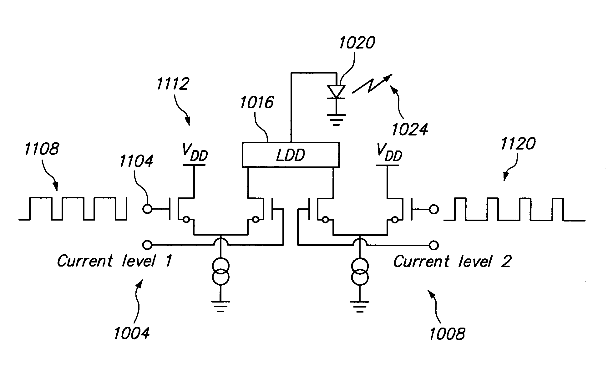
[0041]The term optical signal generator, as used herein is defined to mean any device, element or configuration that emits light. This may include but is not limited to laser, light emitting diode, liquid crystal display, laser diode, gas laser, color center laser, solid state laser, or any other light source that suffers from speckle or other image quality degradation due to light coherence. The term light as used herein may comprise any type or wavelength of light including but not limited to near infrared, far-infrared, visible spectrum, or ultraviolet. The term coherence refers to the broadness of the emission spectrum of the light energy considered. The broadness is typically measured by the wavelength range beyond which—the emitted power drops below half of the peak power. For projector applications an emission width of 1 nm or below is considered “coherent” . Different application might consider different value of spectral broadness as coherent. It is further contemplated tha...


PUM


Abstract

An optical signal generator is configured with an associated control system and driver configured to reduce speckle. Speckle reduction occurs by pulsing the drive signal between a first current level and a second current level. These pulses force the optical signal generator to introduce oscillations into the optical signal. The coherence of the emitted light is reduced during the period of oscillations in the optical signal, which reduces speckle. In one embodiment, the pulsing of the drive signal brings the drive signal down to a level near or below threshold, which in turn intermittently turns off the optical signal output. Returning the optical signal to a desired optical output intensity introduces the speckle reducing oscillation. The pulse frequency, and duty cycle is controlled by a duty cycle control signal to modulate overall optical power and adjust amount of despeckle.

Description

PRIORITY CLAIM[0001]This application claims benefit of and priority to U.S. Provisional Patent Application No. 61 / 019,197 filed on Jan. 4, 2008 entitled Method and Apparatus for Reducing Laser Speckle.FIELD OF THE INVENTION[0002]The invention relates to optical signal generators and in particular to a method and apparatus for reducing speckle in light output from optical signal generators.RELATED ART[0003]Speckle (the appearance dark areas with bright islands from light from a laser or other coherent light source) is a significant issue in many applications where a laser or combination of lasers are employed as light sources. One such application is laser projection. In a laser projection application, lasers (typically 3: red, green and blue) are used as the light source for the projected image. Various systems utilize these light sources to either “scan” through the picture by adjusting the emitted light on a pixel by pixel basis or the lasers are kept at the maximum intensity whil...

Claims


Application Information

Patent Timeline
IPC IPC(8): H01S3/10
CPCH01S5/06209H01S5/06216H01S5/06246H04N9/3161G02B27/48H01S5/042H04N9/3129H01S5/0652
Inventor BAZZANI, CRISTIANODRAPER, DANIELMCDONALD, KEVIN B.
Owner MACOM TECH SOLUTIONS HLDG INC
Why Eureka
Try Eureka