Lens module and electronic device

A technology of lens module and lens assembly, which is applied in the direction of TV, electrical components, telephone communication, etc., can solve the problems affecting the image quality, etc., and achieve the effect of improving sharpness, reducing light spots or spots, and improving image quality

Pending Publication Date: 2022-07-29
TRIPLE WIN TECH JIN CHENG CO LTD
View PDF0 Cites 0 Cited by
  • Summary
  • Abstract
  • Description
  • Claims
  • Application Information

AI Technical Summary

Problems solved by technology

[0003] When the camera shoots a scene under strong light, some strong light from a specific angle may be reflected inside the len

Method used


Image

  • Lens module and electronic device
  • Lens module and electronic device
  • Lens module and electronic device

Examples


Embodiment 1

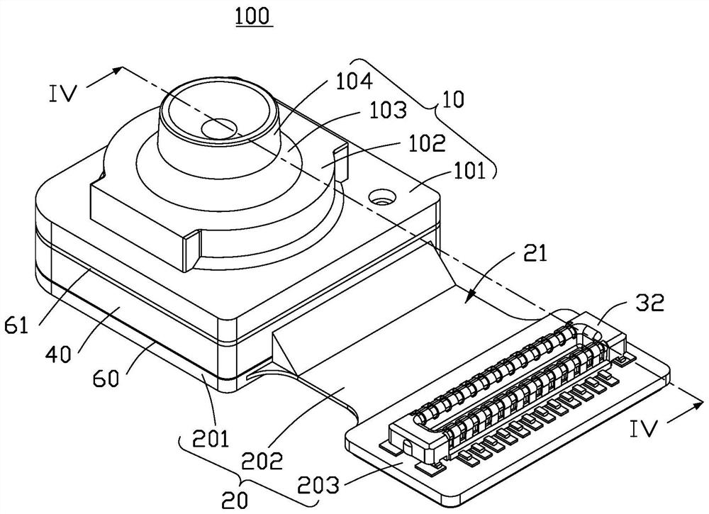
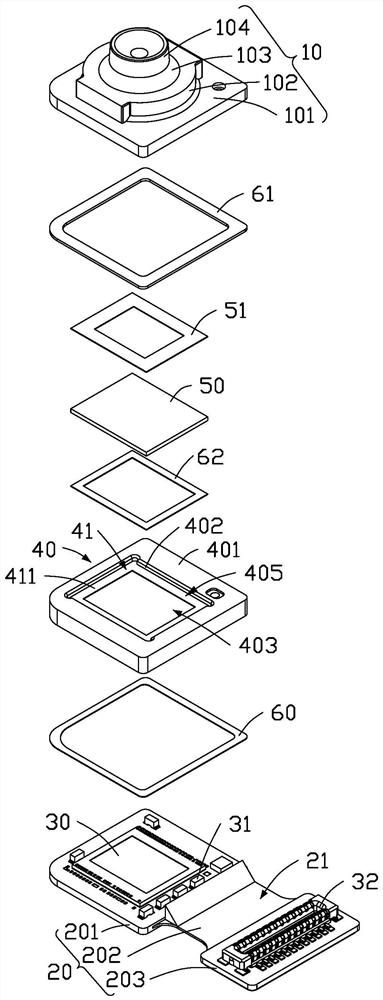
[0071] see Figure 1 to Figure 6 , a preferred embodiment of the present application provides a lens module 100, the lens module 100 includes a circuit board 20 and a lens assembly 10, the lens assembly 10 is arranged on the surface of the circuit board 20, and between the circuit board 20 and the lens assembly 10 A photosensitive chip 30 , a mounting frame 40 and a filter 50 are provided.

[0072] see figure 1 and figure 2, the circuit board 20 includes a first board part 201 , a second board part 202 and a third board part 203 , the lens assembly 10 is mounted on the first board part 201 , and the second board part 202 is connected to the first board part 201 and the third board between sections 203. The surface of the circuit board 20 facing the lens assembly 10 is the base surface 21 . The circuit board 20 can be a flexible board, a rigid board or a rigid-flex board. In this embodiment, the circuit board 20 adopts a rigid-flex board, the first board part 201 and the ...

Embodiment 2

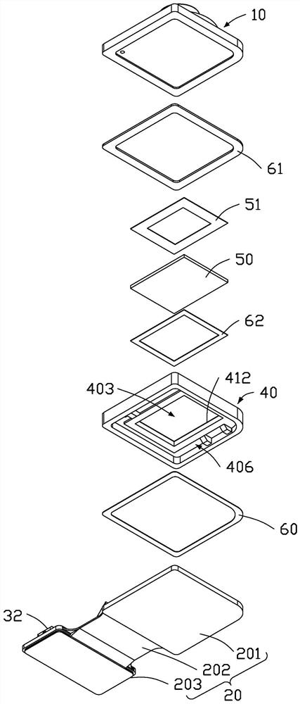
[0087] The difference between the second embodiment and the first embodiment is the structure of the slot 404 .

[0088] see Figure 5 , the mounting bracket 40 includes a bottom surface 4041 and a side surface 4042 at the position where the slot 404 is formed, the bottom surface 4041 is connected with the inner side wall 402 , and the side surface 4042 is connected between the bottom surface 4041 and the top surface 401 . In this embodiment, the bottom surface 4041 is flat and the bottom surface 4041 is perpendicular to the side surface 4042 . The distance between the connection between the bottom surface 4041 and the inner side wall 402 and the supporting surface 411 is smaller than the distance between the surface of the filter 50 away from the circuit board 20 and the supporting surface 411 . In other embodiments, a plurality of slots 404 may also be provided between the top surface 401 and the inner side wall 402, and the plurality of slots 404 form a stepped surface, whi...


PUM


Abstract

The invention provides a lens module which comprises a circuit board and further comprises a lens assembly, an optical filter and a mounting rack, the lens assembly is arranged on one side of the circuit board, and the mounting rack is arranged between the lens assembly and the circuit board; the mounting rack is provided with a through hole penetrating through the mounting rack, the inner side wall of the mounting rack extends towards the central axis of the through hole to form a flange, and the optical filter is mounted on the flange; a first barrier layer is arranged at the edge of one surface, far away from the circuit board, of the optical filter, a second barrier layer is arranged between the optical filter and the inner side wall of the mounting frame, and the surface, far away from the circuit board, of the second barrier layer is higher than the first barrier layer. According to the lens module provided by the invention, the first barrier layer and the second barrier layer can shield some specific strong light more effectively, and the imaging quality of a shot picture is improved. The invention also provides an electronic device using the lens module.

Description

technical field [0001] The present application relates to the technical field of electronics and optical devices, and in particular, to a lens module and an electronic device. Background technique [0002] Electronic products (such as mobile phones or tablets, etc.) often contain cameras. With the development of electronic products, people have put forward higher requirements for the shooting quality and performance of cameras. [0003] When the camera shoots a scene under strong light, some strong light from a specific angle may be reflected inside the lens barrel, and then reflected on the photosensitive chip, causing obvious spots or stains in the image, affecting the image quality. SUMMARY OF THE INVENTION [0004] In view of this, the present application provides a lens module capable of reducing light spots or blemishes in an image. [0005] In addition, it is also necessary to provide an electronic device with the lens module. [0006] The application provides a ...

Claims


Application Information

Patent Timeline
IPC IPC(8): G03B11/00G03B30/00
CPCG03B11/00H04M1/0264H04N23/57H04N23/55H04N23/52
Inventor 宋建超陈信文李静伟丁盛杰
Owner TRIPLE WIN TECH JIN CHENG CO LTD
Why Eureka
Try Eureka