Receiver particularly for a meter-bus

Inactive Publication Date: 2011-07-05
NETWORKED ENERGY SERVICES CORP
View PDF6 Cites 5 Cited by
  • Summary
  • Abstract
  • Description
  • Claims
  • Application Information

AI Technical Summary

Problems solved by technology

The implementation of physical layer presents several challenges especially in the design of a fault tolerant power supply and a receiver.

Method used


Image

  • Receiver particularly for a meter-bus
  • Receiver particularly for a meter-bus
  • Receiver particularly for a meter-bus

Examples


Embodiment Construction

[0011]A receiver particularly suited for M-BUS is described. In the following description, numerous specific details are set forth. It will be appreciated that these details are used to provide a thorough understanding of the present invention, and other circuit configuration and values may be used within the scope of the present invention.

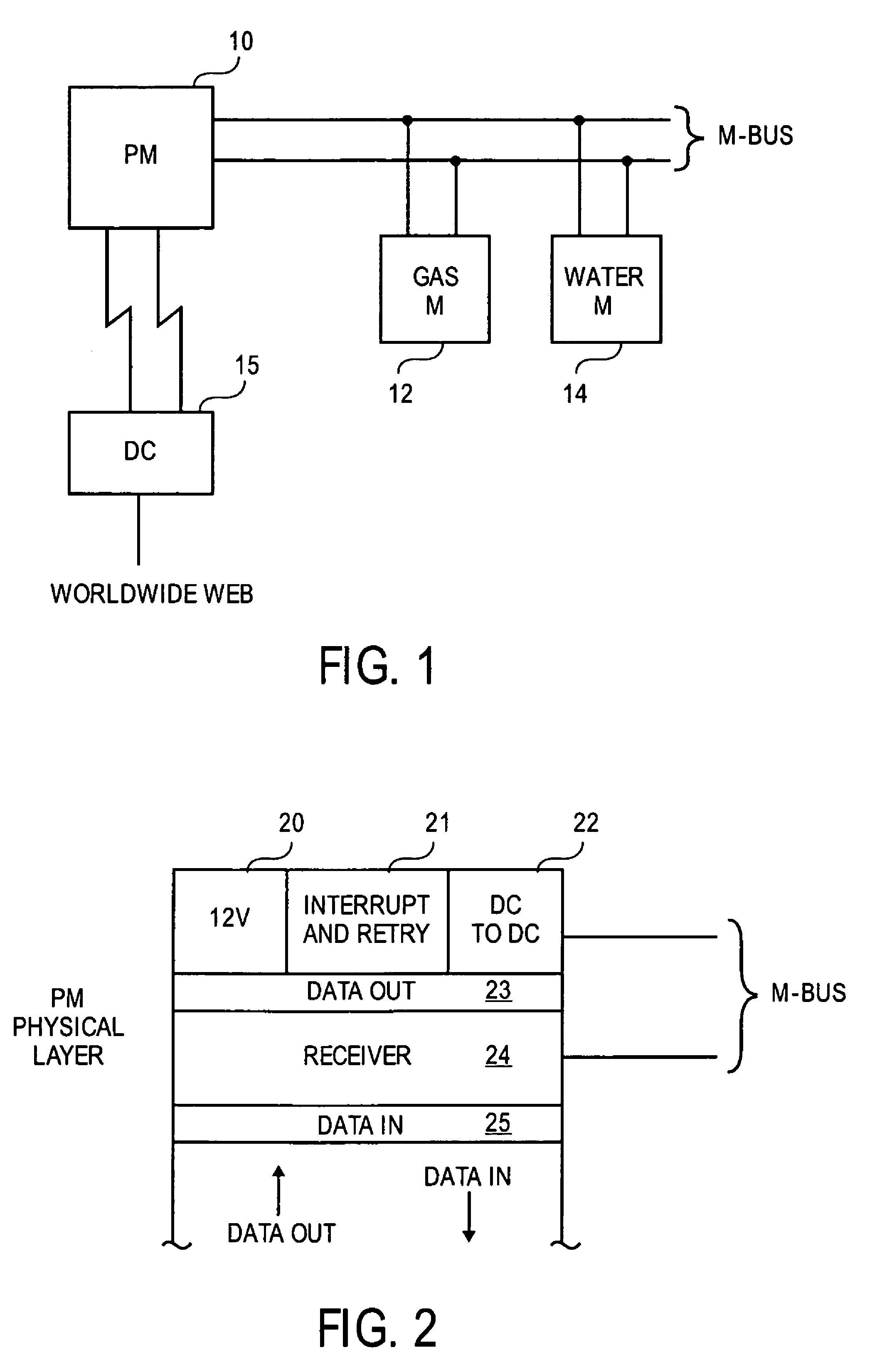
[0012]FIG. 1 illustrates a typical arrangement in which the M-BUS is used. A power meter 10, which is a master under the M-BUS standard, communicates with several slaves such as a gas meter 12 and a water meter 14. The power meter 10, for instance, may poll the gas and water meters to obtain readings over the M-BUS. Several power meters 10 may be coupled to a data concentrator 15 over an RF or IR link, or a hard-wired link. Data concentrators, then may communicate with a central station over, for example, the Internet. Alternatively, the power meter 10 may communicate directly over the Internet with a central station. The meter 10 may communicate ...


PUM


Abstract

A receiver particularly suited for an M-BUS is described. During transmission, the receiver is disabled. After each transmission, nodes and states in the receiver are set to prepare the receiver to receive a signal. Once data is sensed, a feedback loop clips the input signal to the receiver to limit the swing of the input signal. The line of the power supply at the lower potential is modulated, rather than modulating the line at the higher potential, for the transmission of data.

Description

FIELD OF THE INVENTION[0001]The invention relates to the field of receivers for use with signals having a large dynamic range of amplitudes and time.PRIOR ART AND RELATED ART[0002]A standardized serial bus system for the remote reading of meters and various sensors, has been adopted in Europe. The so-called meter-bus or M-BUS permits, for instance, a power meter to act as a master / gateway for other household meters such as gas and water meters. The M-BUS interconnects the master (e.g. power meter) with the slaves (e.g. gas and water meters). Other sensors such as temperature sensors and actuators to, for example, shed electrical loads, may also be coupled to the M-BUS. The physical and link layer of the M-BUS is set forth in EN13757-2 and the application layer in EN13757-3.[0003]The implementation of physical layer presents several challenges especially in the design of a fault tolerant power supply and a receiver. These are discussed in connection with FIGS. 1 and 2.SUMMARY OF THE ...

Claims


Application Information

Patent Timeline
Patent Type & Authority Patents(United States)
IPC IPC(8): H03K19/0175
CPCG01F15/063
Inventor VANRUYMBEKE, GILLESROBINSON, ANDREW
Owner NETWORKED ENERGY SERVICES CORP
Why Eureka
Try Eureka