MBUS (Meter Bus)-based power supply communication device and method

A circuit and constant current charging technology, which is applied in the direction of data exchange through path configuration, data switch current source, data exchange details, etc., can solve the problems of affecting and consuming large current to transmit data signals, etc.

Active Publication Date: 2015-06-03
RUINA INTELLIGENT EQUIP CO LTD
View PDF6 Cites 4 Cited by
  • Summary
  • Abstract
  • Description
  • Claims
  • Application Information

AI Technical Summary

Problems solved by technology

[0005] The purpose of the present invention is to solve the problems existing in the existing MBus-based power supply communication technology, and provide a new MBus-based power supply communication device and method. The problems to be solved include: avoiding the i

Method used


Image

  • MBUS (Meter Bus)-based power supply communication device and method

Examples


Embodiment 1

[0020] Embodiment 1, an MBus-based power supply communication device.

[0021] The MBus-based power supply communication device of this embodiment is connected to both the slave device and the MBus at the same time, that is to say, the MBus-based power supply communication device of this embodiment is an interface device between the slave device and the MBus. After the slave device is connected to the MBus through the device of this embodiment, the slave device can realize MBus-based power supply and information communication.

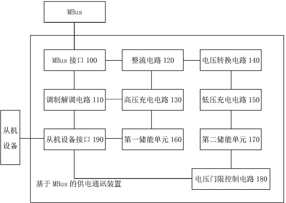
[0022] An example of the structure of the MBUS-based power supply communication device in this embodiment is as follows: figure 1 shown.

[0023] figure 1 Among them, the power supply communication device based on MBUS in this embodiment mainly includes: MBus interface 100, modulation and demodulation circuit 110, rectification circuit 120, high voltage charging circuit 130, voltage conversion circuit 140, low voltage charging circuit 150, first ener...

Embodiment 2

[0042] Embodiment 2, a power supply communication method based on MBus.

[0043] The method of this embodiment mainly includes a data communication step and a rectification step, and the method of this embodiment further includes: at least one of the first power supply step and the second power supply step.

[0044] The data communication steps of this embodiment mainly include: demodulating the voltage pulse sequence in the MBus into a TTL level signal, and transmitting the demodulated TTL level signal to the slave device; The level signal is modulated into a current pulse sequence, and the modulated current pulse sequence is transmitted to the MBus. In addition, since a current is sucked in to realize signal modulation during the modulation process, this embodiment can use the current to charge the first energy storage unit 160 with a constant current during the modulation process.

[0045] The rectification step mainly includes: converting the non-polarity MBus signal in t...


PUM


Abstract

The invention relates to an MBUS-based power supply communication device and method. The device comprises a modulation/demodulation circuit, a rectifying circuit, a high-voltage charging circuit, a voltage conversion circuit, a low-voltage charging circuit and a voltage threshold control circuit; the modulation/demodulation circuit is used for demodulating a voltage pulse sequence in MBus into a TTL (Transistor-Transistor Logic) level signal and transmitting the TTL level signal to slave equipment, and modulating the TTL level signal of the slave equipment into a current pulse sequence and transmitting the current pulse sequence to the MBus; the rectifying circuit is used for converting a nonpolar MBus signal into a 20-42V high-voltage direct-current signal; the high-voltage charging circuit is used for charging a first energy storage unit at a constant current by using the high-voltage direct-current signal; the voltage conversion circuit is used for converting the high-voltage direct-current signal into a low-voltage direct-current signal not more than 5V; the low-voltage charging circuit is used for charging a second energy storage unit at a constant current by using the low-voltage direct-current signal; the voltage threshold control circuit is used for allowing the second energy storage unit to supply electric energy to the slave equipment under the condition that the voltage of the second energy storage unit reaches a preset voltage threshold. According to the device and the method, the stability and the reliability of MBus are improved.

Description

technical field [0001] The invention relates to MBus technology, in particular to an MBUS-based power supply communication device and method. Background technique [0002] MBus (Meter Bus, instrument bus) is a new type of bus structure. Multiple MBus slave devices (also called substations or slave devices) are connected to MBus in parallel, and MBus uses two non-polarity transmission lines to simultaneously realize the power supply and communication of MBus slave devices. [0003] The inventor found in the process of realizing the present invention that: the MBus slave device will consume a large current instantaneously during operation and the like, if the MBus slave device consumes a large current instantaneously during the data signal transmission process of the MBus phenomenon, the phenomenon will adversely affect the data signal transmitted in the MBus. The existing MBUS power supply and communication technology not only cannot avoid this adverse effect, but also has ...

Claims


Application Information

Patent Timeline
IPC IPC(8): H04L12/10H04L12/40
Inventor 陈家培周到于大永
Owner RUINA INTELLIGENT EQUIP CO LTD
Why Eureka
Try Eureka