M-BUS (METER-BUS) slave communication circuit

A technology of M-BUS and communication circuit, which is applied in the field of M-BUS slave communication circuit, can solve the problems of inaccessibility to electric meters and user stealing electricity, etc., and achieve the effect of reducing design cost, small size and design difficulty

Inactive Publication Date: 2015-12-16
谢玉翠
View PDF0 Cites 3 Cited by
  • Summary
  • Abstract
  • Description
  • Claims
  • Application Information

AI Technical Summary

Problems solved by technology

[0002] In some impoverished areas, electricity theft by users is very serious. The power bureau hopes to install the meter measurement unit and the user display unit separately, so that users cannot touch the meter to prevent electricity theft.

Method used


Image

  • M-BUS (METER-BUS) slave communication circuit
  • M-BUS (METER-BUS) slave communication circuit
  • M-BUS (METER-BUS) slave communication circuit

Examples


Embodiment Construction

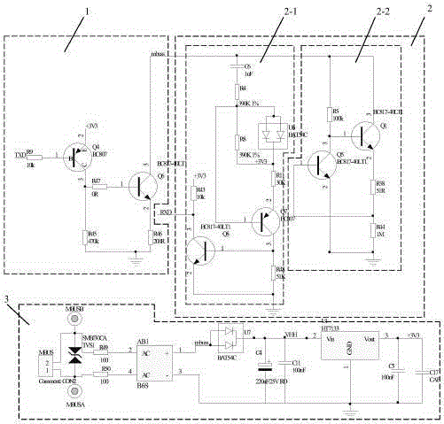
[0023] Such as figure 1 As shown, this embodiment includes a transmitting circuit 1, a _谻, _隽9_ receiving circuit 2 and a power supply circuit 3 respectively connected to the same point mbuss.

[0024] The sending circuit 1 includes a PNP transistor Q4 (model BC807) and an NPN transistor Q6 (model BC817-40LT1), wherein the base of the transistor Q4 is connected to the slave MCU via a resistor R9, and the emitter is connected to a 3.3V power supply. On the one hand, the collector is connected to the base of the transistor Q6 through the resistor R47 (0 ohms), and on the other hand, it is connected to the analog ground through the resistor R45; the collector of the transistor Q6 is connected to the mbuss point, and the emitter is connected to the analog ground through the resistor R46.

[0025] The receiving circuit 2 applies the principle of an RC first-order circuit, including a conversion circuit 2-1 and a constant current source circuit 2-2; wherein,

[0026] The input end ...


PUM


Abstract

The invention relates to an M-BUS (METER-BUS) slave communication circuit. The invention aims at providing an M-BUS slave communication circuit with low cost. According to the technical scheme for solving the problem, the M-BUS slave communication circuit is characterized by comprising a transmission circuit, a receiving circuit and a power supply circuit which are connected to one point mbuss, wherein the transmission circuit comprises a PNP-type triode Q4 and an NPN-type triode Q6, and a collector of the triode Q6 is connected with the point mbuss; the receiving circuit comprises a conversion circuit, wherein the input end of the conversion circuit is connected with the point mbuss, the output end of the conversion circuit is connected to a slave MCU, and the conversion circuit is used for converting the high-low electrical level at the point mbuss into a stable high-low electrical level signal which can be recognized by the slave MCU. The M-BUS slave communication circuit is mainly used for constructing a communication network among an intelligent electric meter, a customer display unit, a water meter and a gas meter.

Description

technical field [0001] This application relates to an M-BUS slave communication circuit, which is mainly used to construct a communication network among smart electric meters, user display units, water meters and gas meters. Background technique [0002] In some poverty-stricken areas, electricity theft by users is very serious. The power bureau hopes to install the meter measurement unit and the user display unit separately, so that users cannot touch the meter to prevent electricity theft. In some developed areas, more and more customers hope to connect water meters and gas meters through electric meters to realize a three-meter data collection system for electric meters, water meters and gas meters. [0003] Therefore, in the design of smart meters, not only the function of electric energy measurement is required, but also the information interaction with the customer display unit (Customer Interface Unit) and the collection of information such as water meters and gas met...

Claims


Application Information

Patent Timeline
Patent Type & Authority Applications(China)
IPC IPC(8): G08C19/28G06F13/40
Inventor 谢玉翠
Owner 谢玉翠
Why Eureka
Try Eureka