Semi-constrained 1st carpometacarpal implant arthroplasty and method

a carpometacarpal and implant technology, applied in the field of carpometacarpal (cmc) arthroplasty, can solve the problems of pain in the movement of the 1st cmc joint, and achieve the effect of improving the stability and stability of the join

Active Publication Date: 2011-07-12
MAYO FOUND FOR MEDICAL EDUCATION & RES
View PDF14 Cites 19 Cited by
  • Summary
  • Abstract
  • Description
  • Claims
  • Application Information

AI Technical Summary

Problems solved by technology

Movement of the 1st CMC joint occasionally becomes painful.

Method used


Image

  • Semi-constrained 1st carpometacarpal implant arthroplasty and method
  • Semi-constrained 1st carpometacarpal implant arthroplasty and method

Examples


Embodiment Construction

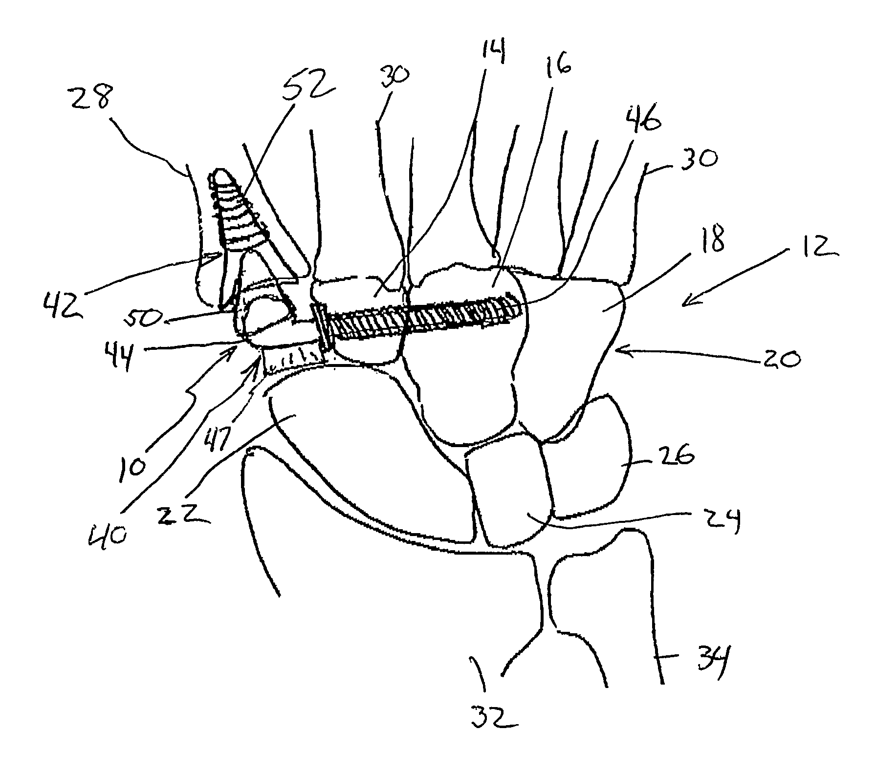
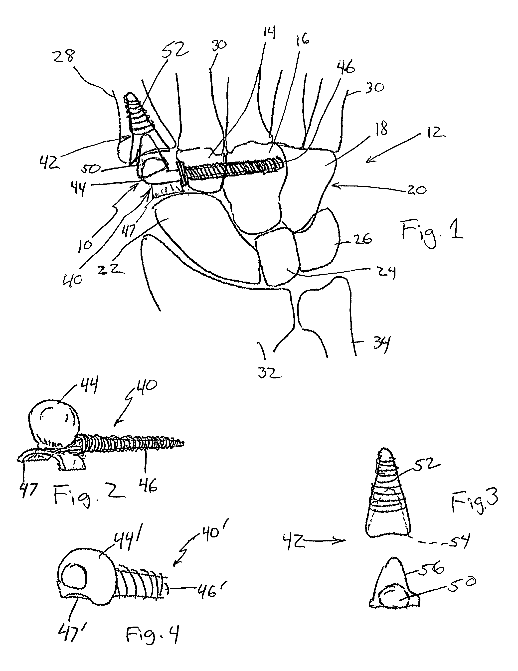
[0009]FIG. 1 is an illustration of a 1st carpometacarpal (CMC) joint implant 10 in accordance with one embodiment of the present invention mounted to bones in the hand 12 of a patient. Illustrated wrist bones of the hand 12 include the trapezoid 14, capitate 16 and hamate 18 of the distal carpal row 20, scaphoid 22, lunate 24 and triquetrum 26. Metacarpal 28 of the thumb (the first metacarpal), as well as the metacarpals 30 of the other four fingers are also shown, as is the radius 32 and ulna 34 of the arm. The implant 10 includes a proximal component 40 mounted to and extending from the distal carpal row 20, and a distal component 42 that is mounted to and extends from the thumb metacarpal 28. Proximal component 40 and distal component 42 cooperate as a joint to enable relative movement between metacarpal 28 and trapezoid 14.

[0010]As shown in both FIGS. 1 and 2, the proximal component 40 of implant 10 includes a joint portion 44 and a fixation portion 46. Fixation portion 46 is lo...


PUM


Abstract

A first carpometacarpal joint implant. One embodiment of the invention includes proximal and distal components. The proximal component includes a fixation portion for attachment to one or more elements of a patient's distal carpal row, a ball-type joint portion cantilevered off the fixation portion, and a skid having a concave surface opposite the ball-type joint for engaging a patient's scaphoid bone. The distal component has a fixation portion for attachment to a patient's thumb metacarpal, and a socket-type joint portion that cooperates with the ball-type joint portion of the proximal component.

Description

REFERENCE TO RELATED APPLICATION[0001]This application claims the benefit of U.S. Provisional Application Ser. No. 60 / 709,163, filed Aug. 18, 2005, and entitled SEMI-CONSTRAINED 1ST CARPOMETACARPAL IMPLANT ARTHROPLASTY, which is incorporated herein by reference in its entirety.FIELD OF THE INVENTION[0002]The present invention relates generally to carpometacarpal (CMC) arthroplasty. In particular, the invention is an implant and procedure for theist CMC joint located at the base of the thumb.BACKGROUND OF THE INVENTION[0003]The joint at the base of the thumb is known as the 1st carpometacarpal (CMC) joint. The bone at the base of the thumb is known as the thumb metacarpal. The trapezium is the bone in the wrist adjacent to the thumb metatacarpal.[0004]Movement of the 1st CMC joint occasionally becomes painful. Reasons for pain of this type include trauma and arthritis. A variety of surgical procedures can be performed to alleviate 1st CMC joint pain. In one surgical procedure, the tr...

Claims


Application Information

Patent Timeline
Patent Type & Authority Patents(United States)
IPC IPC(8): A61F2/42
CPCA61F2/4241A61F2002/4256
Inventor BERGER, RICHARD A.
Owner MAYO FOUND FOR MEDICAL EDUCATION & RES
Why Eureka
Try Eureka