Shock dampening post driver

a post driver and shock dampening technology, applied in the field of post drivers, can solve the problems of affecting the use of the post driver, so as to reduce the vibration and shock, and reduce the force transferred

Active Publication Date: 2011-07-19
WILSON ROBERT
View PDF26 Cites 10 Cited by
  • Summary
  • Abstract
  • Description
  • Claims
  • Application Information

AI Technical Summary

Benefits of technology

[0011]A user can grasp the handles and lift the device over a post such that the post is aligned with the opening at the bottom of the shaft. The user can then force the shaft down over the post such that the post enters the interior cavity through the downward facing opening and strike the closed top end of the shaft. This creates vibration and shock in the shaft, but the dampening springs between the shaft and the handles greatly reduce the vibration and shock reaching the handles held by the user, thus reducing the force transferred to the hands, arms and wrist of the user.

Problems solved by technology

Historically, fence builders used large hammers to drive posts, though this was backbreaking—and often dangerous—work.
However, these traditional post driving devices caused a great deal of vibration and tended to be very jarring to the hands and wrist of the user.
Users of these post driving devices often experienced pain in their arms and back and typically experienced discomfort in their hands after repeated use.
However, these newer post driving devices with springs internal to the post tube are limited in that the size and number of springs utilized is limited, and thus the dampening ability is minimal.
While better than traditional post driving devices that have little or no impact dampening abilities, even these newer post driving devices do not contain sufficient impact dampening capabilities for many people who need to drive a large number of posts.
Also, the location of the dampening spring is not effective for dampening the forces transferred from the handles to the hands or wrist of the user.

Method used


Image

  • Shock dampening post driver
  • Shock dampening post driver
  • Shock dampening post driver

Examples


Embodiment Construction

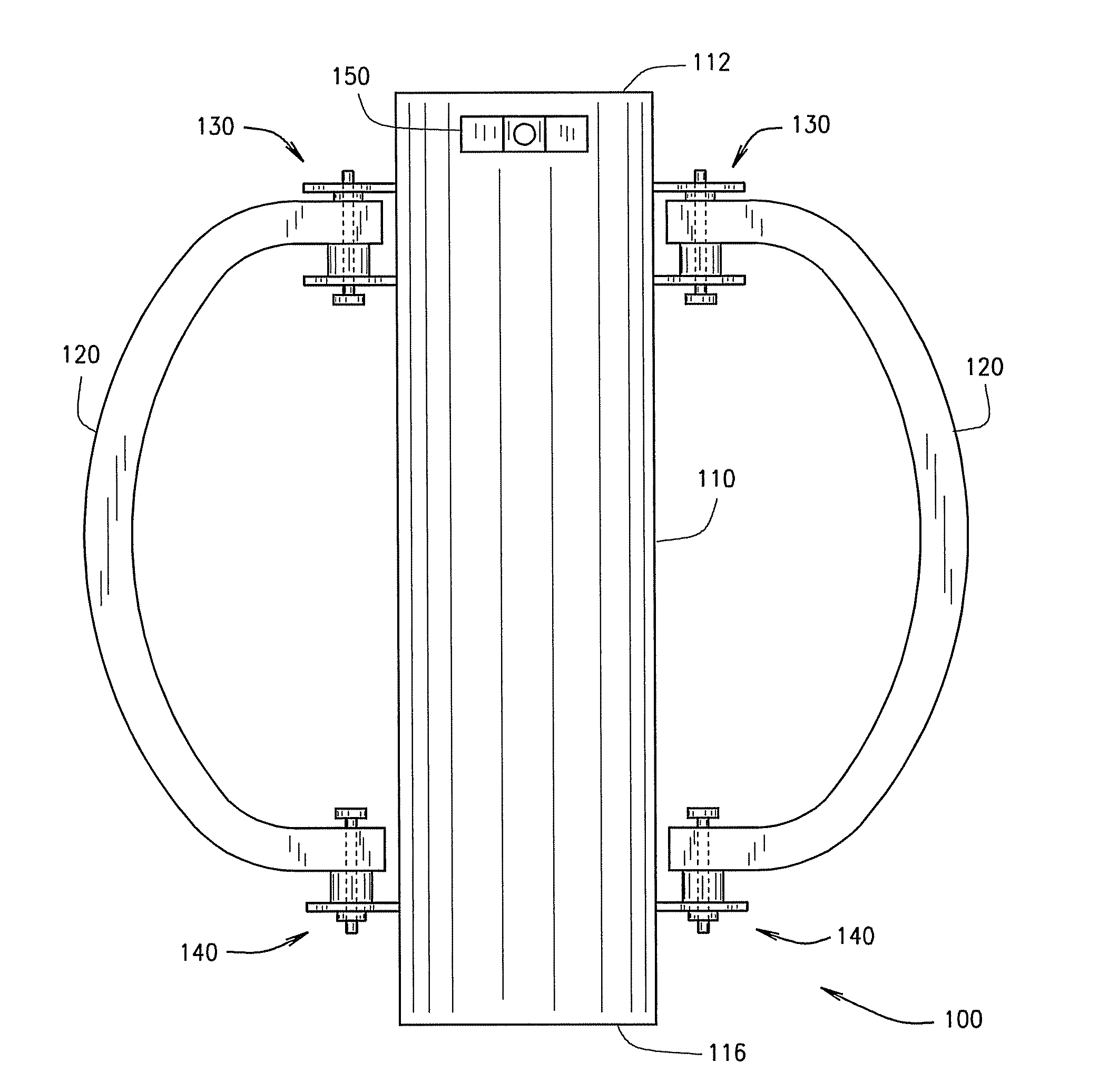
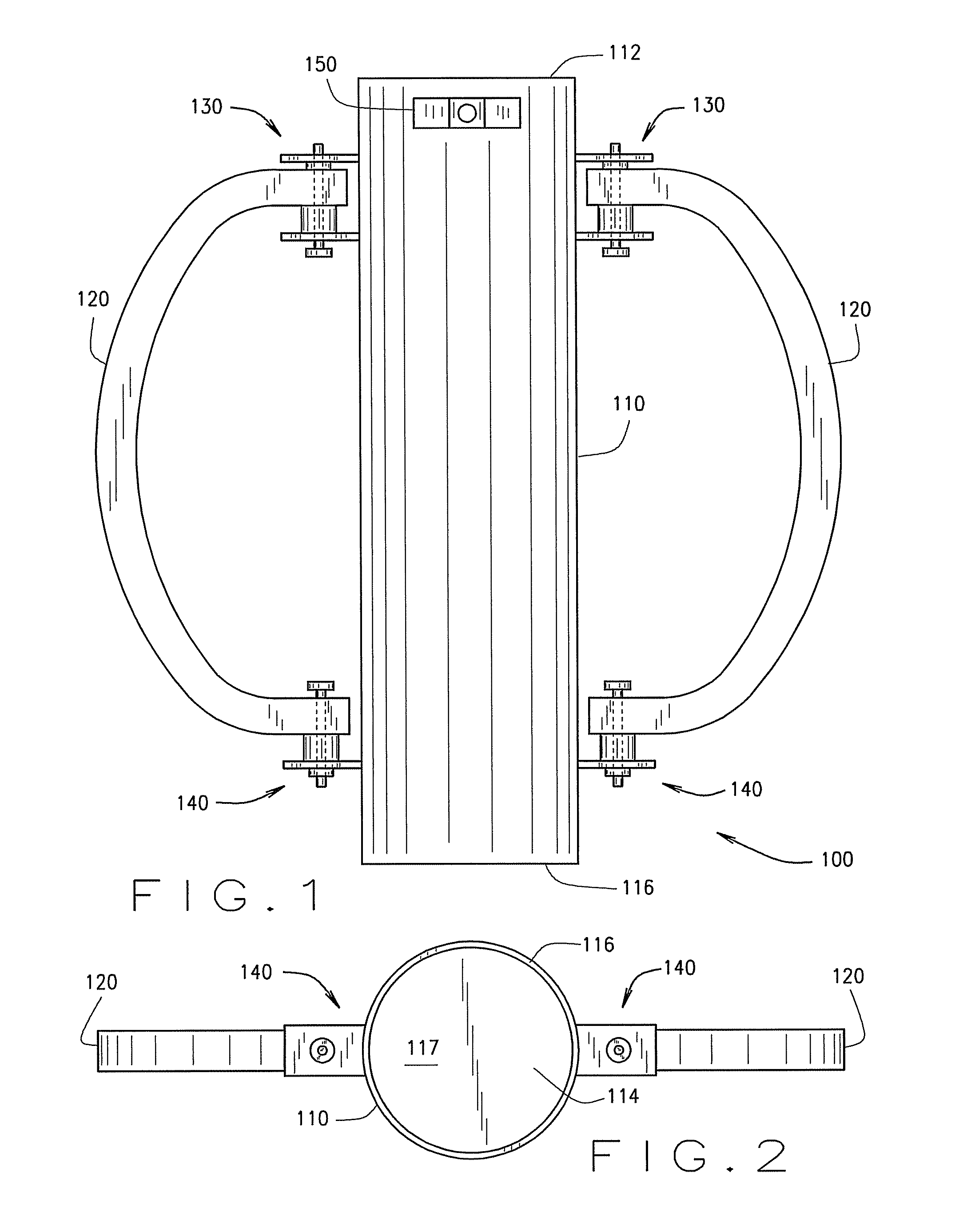
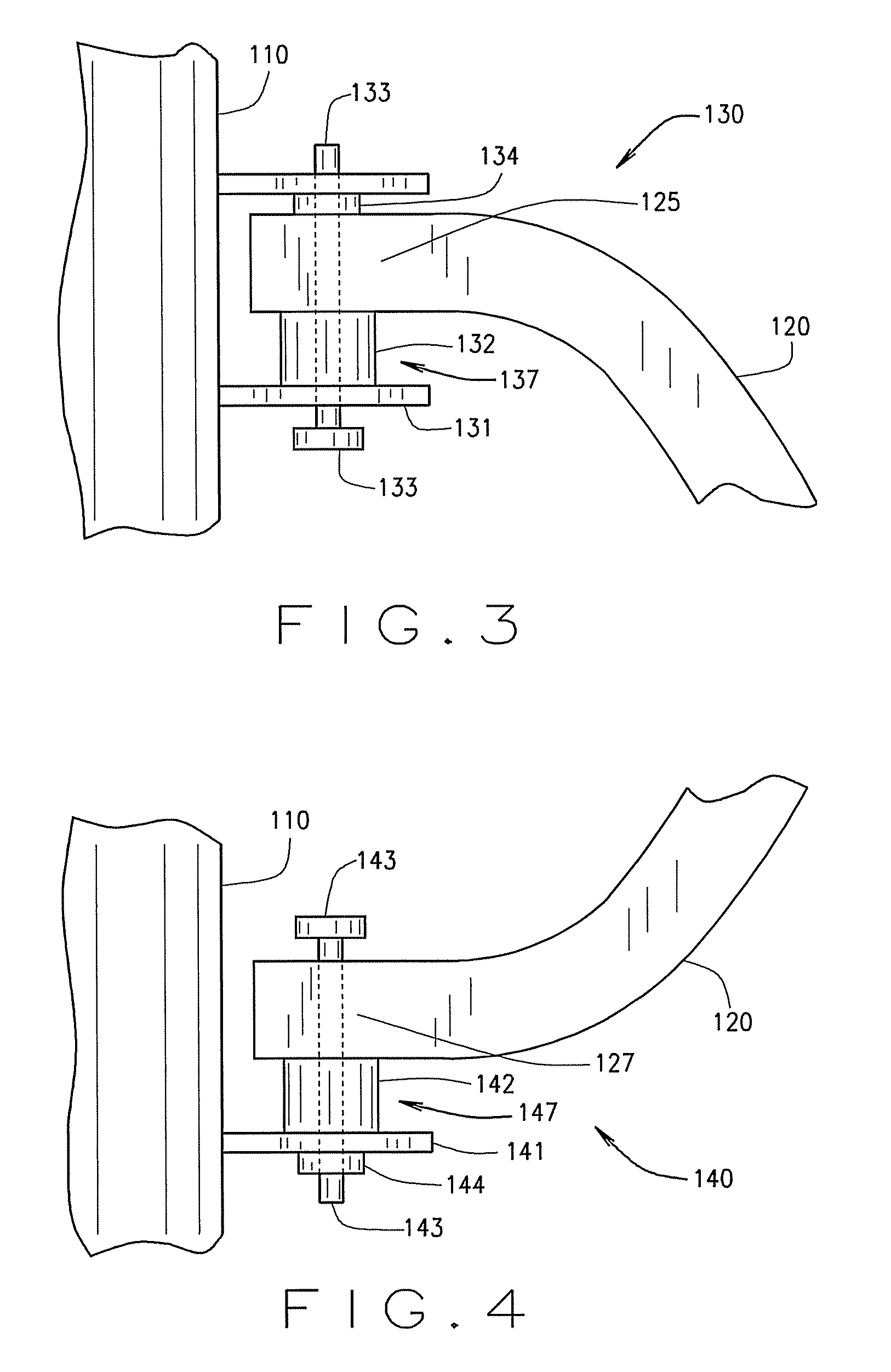
[0019]A shock-dampening post driving device, according to an embodiment of the present invention, includes a shaft having an axially extending interior cavity that extends to a closed top end of the shaft and to a distal open bottom end of the shaft. The closed top end of the shaft forms a striking surface that is used to strike posts. The shaft also has a first mounting bracket extending from an exterior wall of the shaft. Additionally, an upper mounting flange of a handle is mounted to the first mounting bracket of the shaft by a first floating mount with a first floating region. Further, a first dampening spring is positioned between the upper mounting joint of the handle and the first mounting bracket. This first dampening spring extends into the first floating region, where it dampens vibration between the shaft and the handle.

[0020]Another embodiment of a shock-dampening post driving device includes a handle mounted to a shaft by a first floating mount having a first floating ...


PUM


Abstract

A post driver having a dampening device adapted to isolate the hands and arms of the user from shock.

Description

BACKGROUND OF INVENTION[0001]1. Field of Invention[0002]The present invention relates to a post driver. More specifically, the present invention relates to a vibration dampening post driver for driving posts into the ground more comfortably and with less risk of injury.[0003]2. Background Art[0004]Fences have been used to mark territorial boundaries, prevent trespassers from entering a property, and contain livestock. These fences require that hundreds or thousands of posts be driven into the ground at regular or evenly spaced intervals. Historically, fence builders used large hammers to drive posts, though this was backbreaking—and often dangerous—work.[0005]There have been some advances in the post driving art area. Cylindrical post driving devices, such as that shown in Hunt, U.S. Pat. No. 2,098,146—including a post tube, which is open only at the bottom of the tube, and handles on both sides of the tube—were invented long ago. In use, these post driving devices were positioned w...

Claims


Application Information

Patent Timeline
Patent Type & Authority Patents(United States)
IPC IPC(8): B25D17/24
CPCE04H17/263
Inventor WILSON, ROBERT
Owner WILSON ROBERT
Why Eureka
Try Eureka