Hole opener assembly and a cone arm forming a part thereof

a technology of cone arms and opening parts, which is applied in the field of hole openers, can solve the problems of affecting the operation of the hole opener, the hole may be clogged, and the hole may need to be rebuilt, so as to achieve tighter fit and reduce the effect of force transfer

Active Publication Date: 2010-08-19
CENTURY PRODS CALIFORNIA
View PDF20 Cites 4 Cited by
  • Summary
  • Abstract
  • Description
  • Claims
  • Application Information

AI Technical Summary

Benefits of technology

[0009]An improved hole opener assembly is disclosed that is less prone to failure as a result of cone arm break out or pocket fracture. The hole opener assembly includes a bit body extending along a rotational axis. A plurality of pockets is formed in the bit body. Each of the pockets has a wall defining at least a portion of the pocket. The hole opener assembly further includes a plurality of cone arms each having an arm with an attached cone head. Each arm is mounted into one of the pockets to form an interface therebetween. At least one of the interfaces includes a slot formed in one of the pocket and the arm and a key formed in the other of the pocket and the arm. When the arm is inserted into the pocket, the key mates with the slot. The key and the slot have a tighter fit therebetween than between the arm and the pocket. Hence, a force exerted on the arm is initially transferred across the key and the slot to reduce the force transferred from the arm to the wall of the pocket.

Problems solved by technology

Under the extreme stress of the drilling operation, cone arms can fracture from the bit body.
However, in many cases, a wall of the pocket may fracture and this wall will need to be rebuilt.
Thus, any cone arm failure or “break out” can be costly as the cone arm may need to be discarded or, if possible, repaired.
This may result in substantial downtime, upsetting the construction schedule.

Method used


Image

  • Hole opener assembly and a cone arm forming a part thereof
  • Hole opener assembly and a cone arm forming a part thereof
  • Hole opener assembly and a cone arm forming a part thereof

Examples


Embodiment Construction

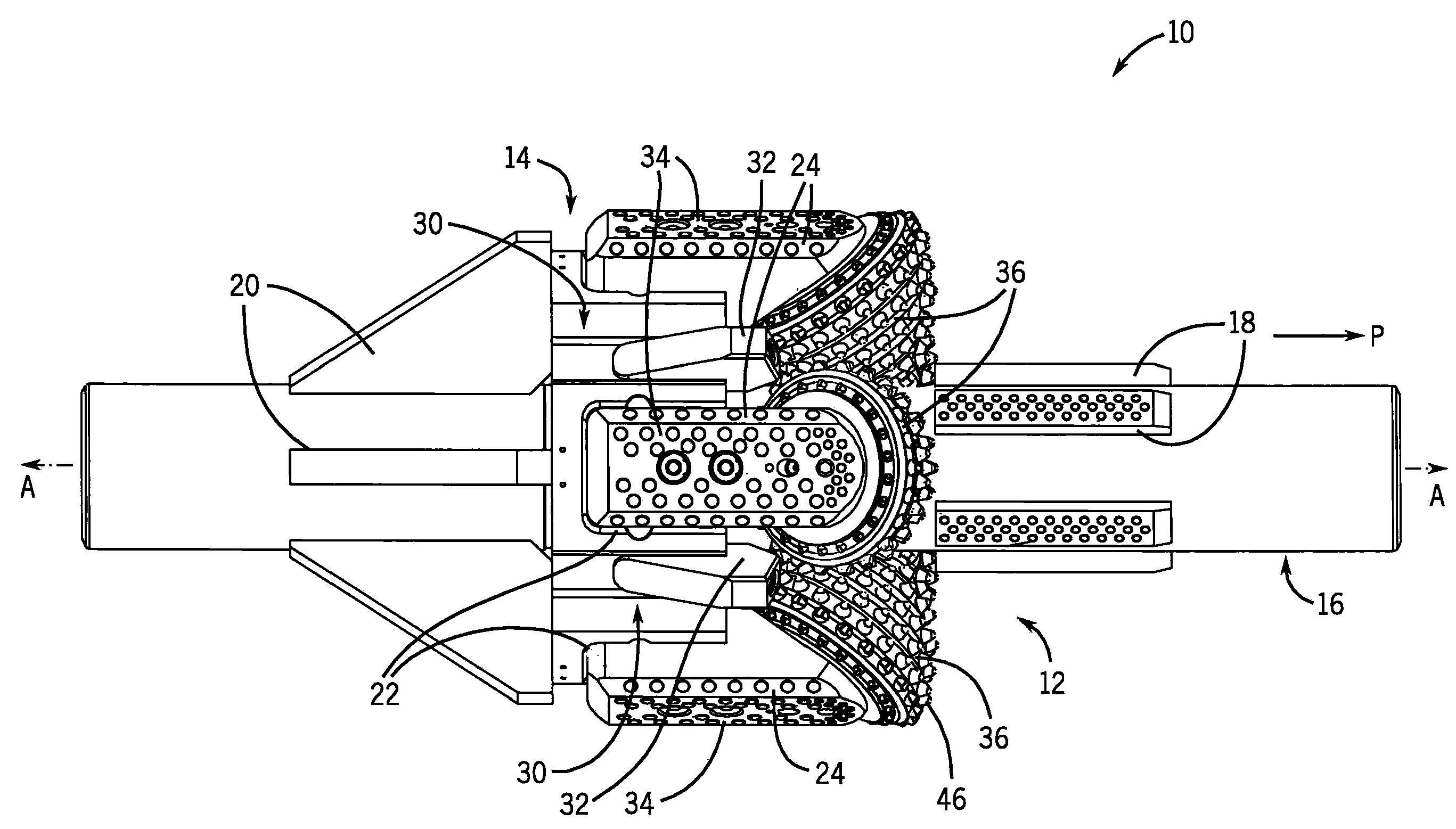
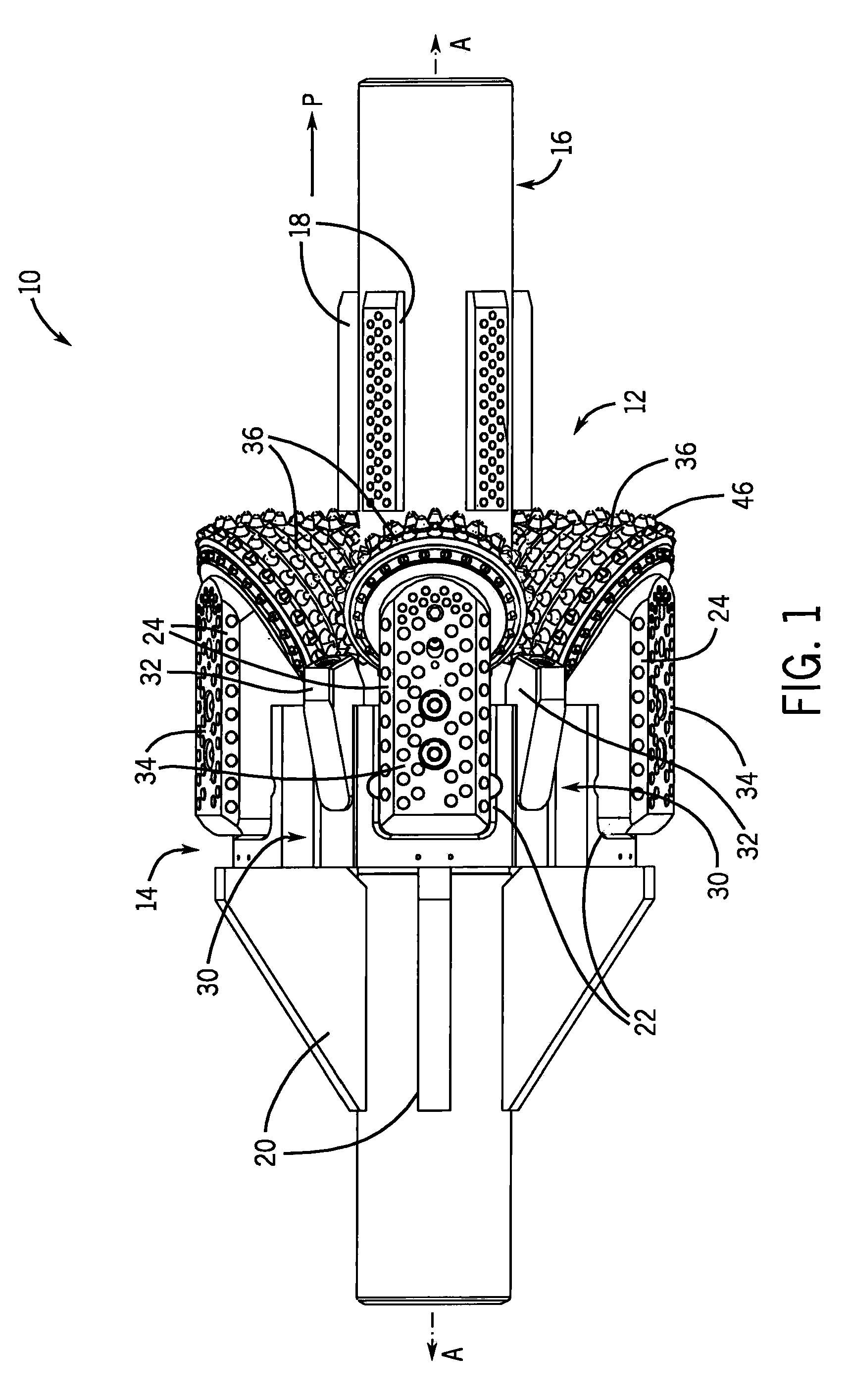
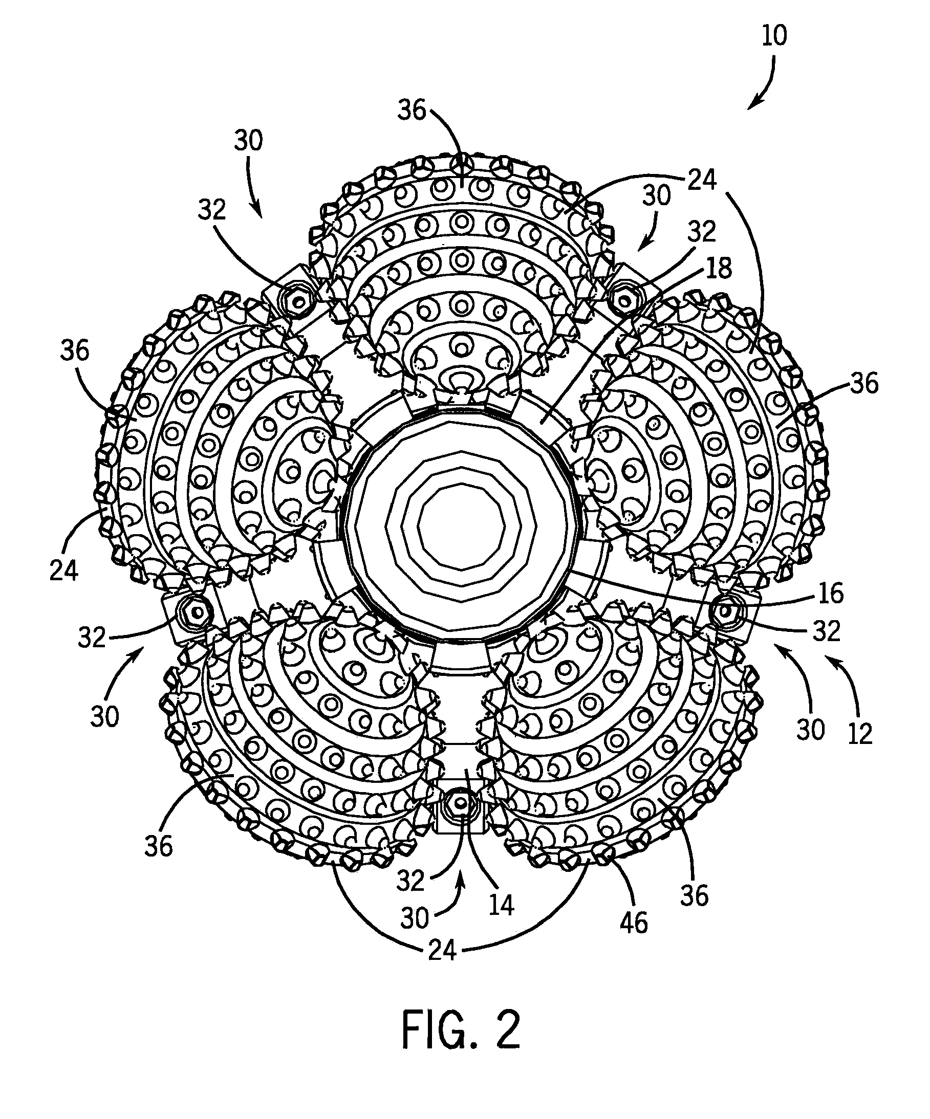
[0022]Referring first to FIGS. 1-3, a hole opener assembly 10 is shown for pulling or pushing in a drill direction P. The hole opener assembly 10 includes a bit body 12 that extends along a rotational axis A-A which is parallel to the drill direction P. The bit body 12 has a solid body 14 with a shaft 16 extending axially therethrough. The shaft 16 is hardened (such as to approximately 40 HRC) and is welded to the solid body 14. A set of front stabilizers 18 and a set of rear stabilizers 20 extend from the shaft 16 to the solid body 14 to increase the strength of the bit body 12. The front stabilizers 18 and the rear stabilizers 20 are generally fin-shaped.

[0023]With additional reference to FIGS. 4-10, the solid body 14 has a plurality of pockets 22 formed about its outer periphery. Each of the pockets 22 are adapted to receive one of a plurality of cone arms 24 as will be described in further detail below. The pockets 22 are evenly angularly spaced about the rotational axis A-A of ...


PUM


Abstract

An improved hole opener assembly for horizontal drilling is disclosed that is less prone to failure as a result of cone arm break out or pocket side wall fracture. The interface between the cone arm and the pocket employs a key and slot configuration with a tighter fit than between the arm and the pocket to reduce the stress on the pocket side wall during drilling.

Description

CROSS-REFERENCE TO RELATED APPLICATION[0001]Not applicable.STATEMENT OF FEDERALLY SPONSORED RESEARCH OR DEVELOPMENT[0002]Not applicable.BACKGROUND OF THE INVENTION[0003]This invention relates to hole openers for horizontal directional drilling. In particular, this invention relates to the attachment of cone arms to the bit body of hole openers.[0004]During the installation of pipes, conduits, or other types of lines, it may be necessary to provide a horizontal pathway through areas that are not easily excavated. Such areas may include preexisting structures, environmentally sensitive areas, areas in which there is high traffic flow, and the like.[0005]One method used to create a pathway without excavation is horizontal directional drilling. In horizontal directional drilling, a pilot hole is drilled along the pathway. After the pilot hole is drilled, a hole opener is pulled and / or pushed back through the pilot hole to enlarge the diameter of the hole to the desired size.[0006]Typica...

Claims


Application Information

Patent Timeline
Patent Type & Authority Applications(United States)
IPC IPC(8): E21B10/08E21B10/20
CPCE21B10/28
Inventor BIELAWA, TODDSCHULZ, JAMES
Owner CENTURY PRODS CALIFORNIA
Why Eureka
Try Eureka