Linear light source device for image reading

a light source device and image reading technology, applied in the field of light sources, can solve the problems rational and not rigorous precision requirements, etc., and achieve the effect of low fabrication cost of molds or tooling and simple structure and configuration

Inactive Publication Date: 2005-02-08
PIXON TECH CORP
View PDF16 Cites 88 Cited by
  • Summary
  • Abstract
  • Description
  • Claims
  • Application Information

AI Technical Summary

Benefits of technology

An objective of the invention is to provide a linear light source device used for image reading. The light-guide bar is simple in structure and configuration, thereby; the precision requirements are rational and not rigorous. As a result, the fabrication cost for the mold or tooling is low. Moreover, the reflective plane having surface stripes with reflective function are surface treated for surface roughness, the reflecting paint can be but does not have to be spread or coated. Therefore, the manufacturing yield of an ideal light-guided bar is easy to achieve.

Problems solved by technology

The light-guide bar is simple in structure and configuration, thereby; the precision requirements are rational and not rigorous.
As a result, the fabrication cost for the mold or tooling is low.

Method used


Image

  • Linear light source device for image reading
  • Linear light source device for image reading
  • Linear light source device for image reading

Examples


Embodiment Construction

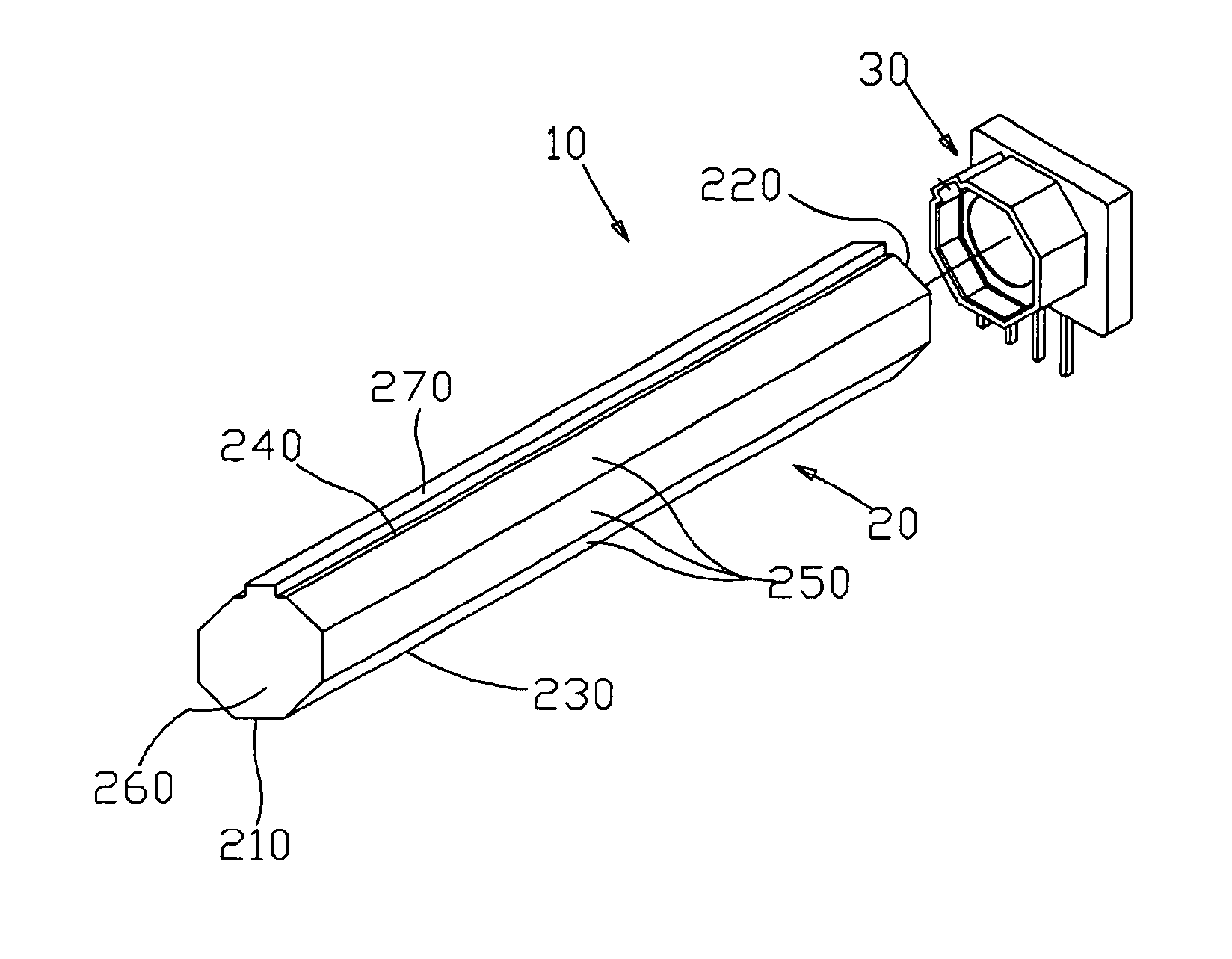
Refer to FIG. 11, which is an isometric view of a preferred embodiment of the invention. As shown in FIG. 11, the linear light source 10 of the invention comprises a light-guide bar 20 and a light source assembly 30. Essentially, the light-guide bar 20 is an octagonal polygonal main body, and being a symmetrical octagonal column 210, it is selected as a preferred embodiment of the invention. The symmetrical octagonal column 210 includes: an incident plane 220 having at least an end into which the light beam is allowed to enter while the other end can be a tail end 260; a reflective plane 230; a light-exiting plane 270; and a plurality of reflective layers 250. A long protruding strip is provided on a side surface of the symmetrical octagonal column 210 and is used as the light-exiting plane 270. On either side of the light-exiting plane 270 are reflecting strips 240 for reflecting light that slightly misses the light-exiting plane 270. The reflective plane 230 and the light-exiting ...


PUM


Abstract

A linear light source device for image reading. The main body of the linear light source device includes at least a light-guide bar and a light source assembly. The light-guide bar is a polygonal column with one surface having stripes thereon, acting as a reflective plane with a reflective function. The opposite plane to the reflective plane is a light-exiting plane, and all the remaining planes are reflective layers. At least one of the ends of the polygonal column is an incident plane for a light beam to enter. Light is transmitted through both of the two ends of the polygonal column (or one end with the other end acting as a reflective plane) and uniformly transmits through the light-exiting plane. The light-guided bar has a simple structure and configuration, a compact volume, a high rate of utilization in light energy, is flexibly changed in length, and is easy to manufacture with high product yield and low manufacturing cost. In addition, it can provide uniform monochromatic and colored light, with high luminance, and at a low cost.

Description

FIELD OF THE INVENTIONThe invention relates to a light source, and more particularly to a linear light source device for image reading in equipment, such as scanners, facsimile machines, multifunction office machines, and copy machines.BACKGROUND OF THE INVENTIONAn image reading device such as a scanner, facsimile machine, multi-function office machine, and copy machine etc. needs a linear light source to illuminate the targets while liquid crystal modules needs to have an illuminated background. The method utilizes a light source combined with a light-guide bar so as to transfer the light source into a linear light source, in this way, the backlight can be provided for a liquid crystal panel.Conventional linear light source devices for image reading are as follows: (1) utilize a cold cathode ray tube (CRT) as the linear light source 110 as shown in FIG. 1; (2) utilize a light-emitting diode (LED) array for the linear light source 120 as shown in FIG. 2; (3) utilize an LED array plu...

Claims


Application Information

Patent Timeline
Patent Type & Authority Patents(United States)
IPC IPC(8): H04N1/028
CPCH04N1/02815H04N1/0289H04N1/0284H04N1/0282
Inventor WU, RONG-YAWPANG, MING-JEN
Owner PIXON TECH CORP
Why Eureka
Try Eureka