
System and method for debugging a software program

a software program and system technology, applied in the field of system and method for debugging software programs, can solve the problems of consuming considerable time and consuming a large amount of time to compile, and achieve the effect of accurately and efficiently matching the measurement and control requirements of users and simple configuration process

Inactive Publication Date: 2003-10-09
NATIONAL INSTRUMENTS
View PDF28 Cites 164 Cited by
  • Summary
  • Abstract
  • Description
  • Claims
  • Application Information

AI Technical Summary

Benefits of technology

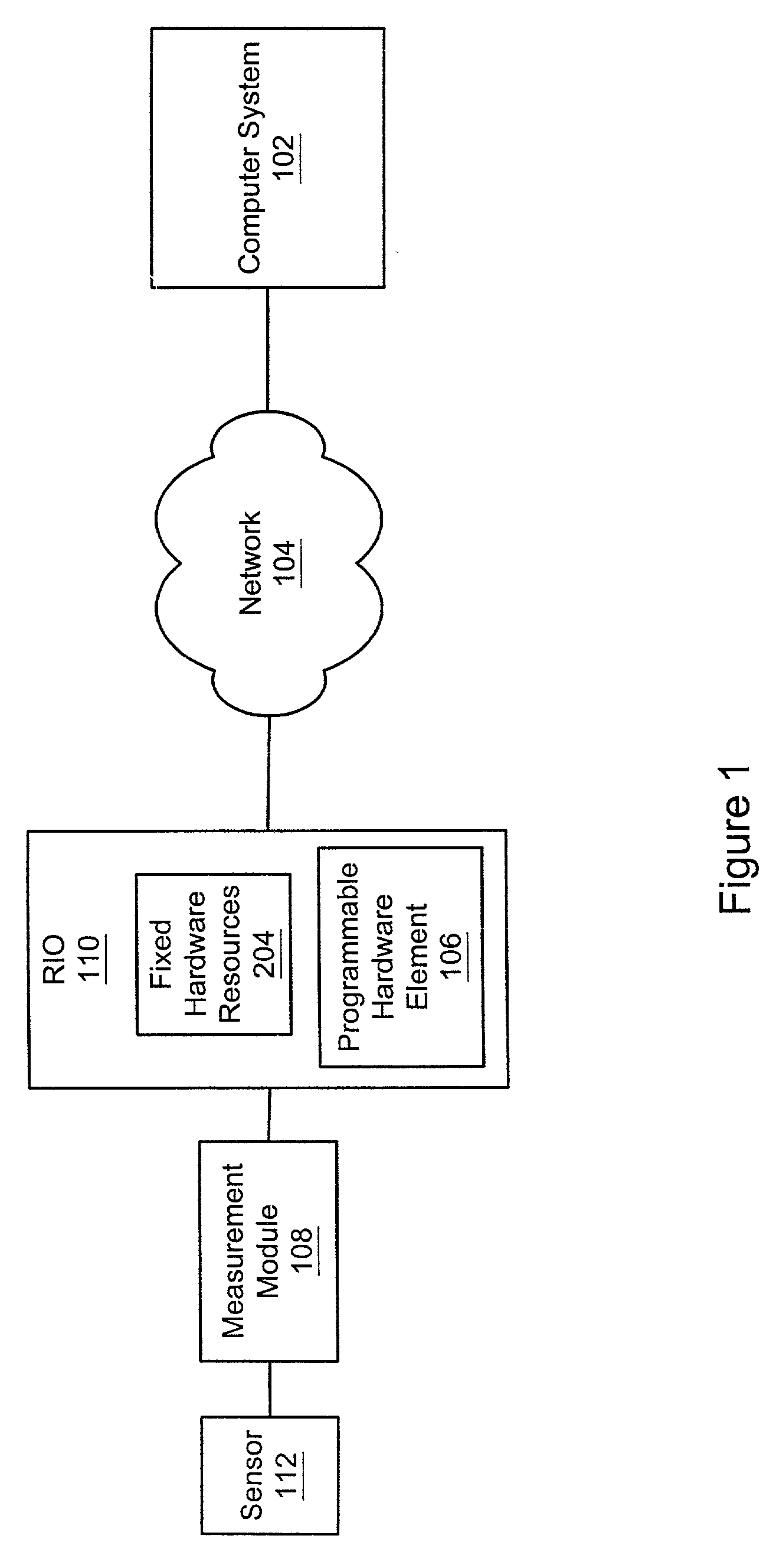
[0054] Finally, the computer system may execute the program for test and analysis. Executing the program includes the program communicating with the one or more fixed hardware resources through the programmable hardware element. In other words, the computer system may execute the program while maintaining connectivity with the one or more fixed hardware resources via the test feed-through configured programmable hardware element, and thus interacting with the "real world" signals and behavior of the hardware resources. This allows both fast and accurate testing of programs to be deployed on the RIO device.
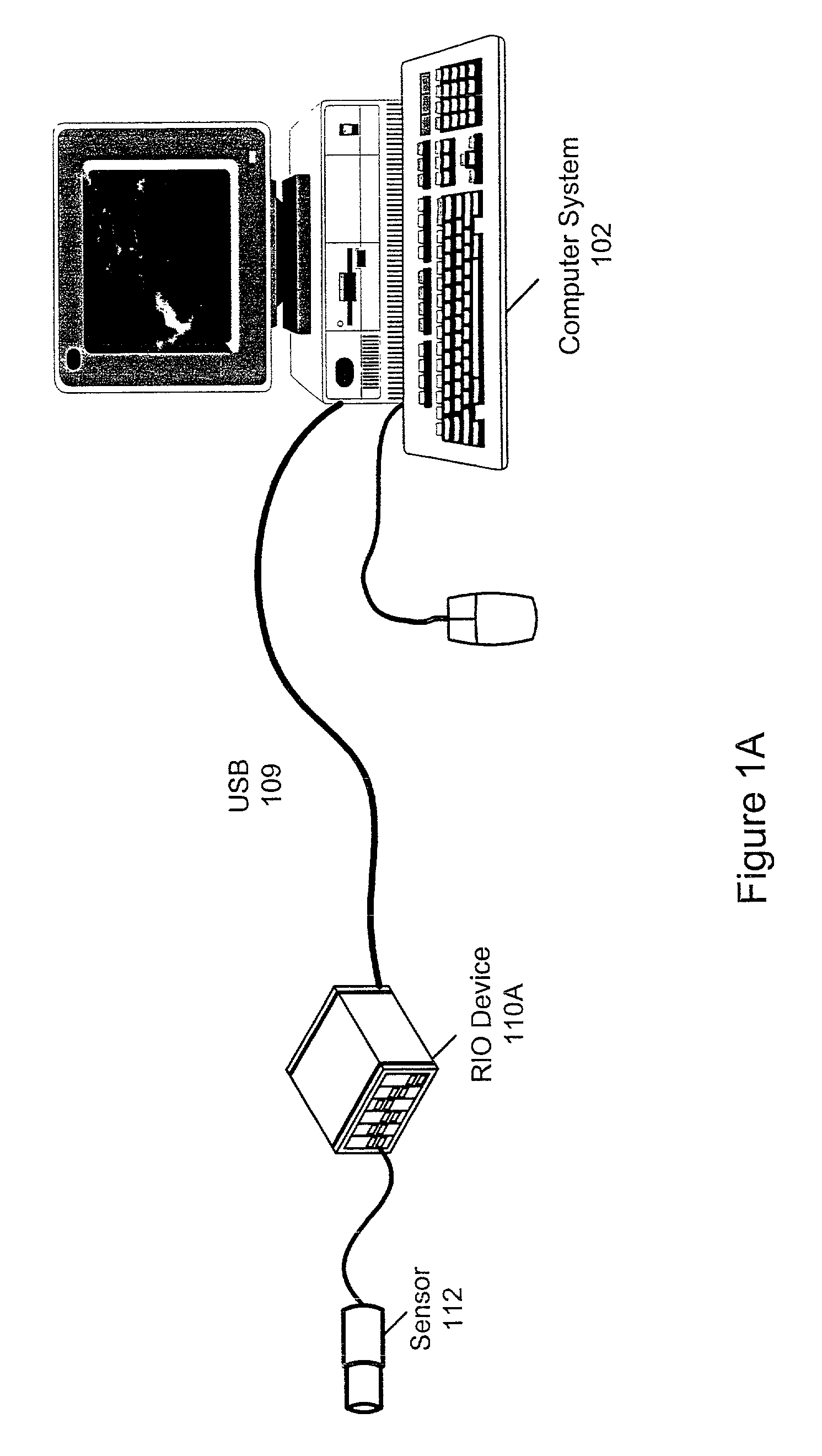
[0084] Thus, the use of RIO devices in combination with a variety of platforms and computer systems provides a broad range of approaches for efficient and flexible measurement systems, including established platforms such as PCI / PXI and FieldPoint, USB / Ethernet devices, and small networked measurement nodes (e.g., smart sensors) for highly distributed measurement systems. Additionally, the adaptive (i.e., programmable) aspect of RIO systems in conjunction with measurement modules provides measurement and control solutions which may more accurately and efficiently match the measurement and control requirements of users. Finally, the use of graphical programs to configure the RIO hardware may greatly simply the configuration process.

Problems solved by technology

Often, the field signals may comprise high common-mode voltages, ground loops, or voltage spikes that often occur in industrial or research environments which could damage the computer system.
In general, compile times for generating a hardware configuration program for an FPGA may take a lengthy time, e.g., many hours.
When targeting the hardware (i.e., the programmable hardware element) these I / O primitives (possibly including standard LabVIEW primitives) may be converted into a hardware representation, such as an FPGA program file, as described above, and may take considerable time to compile.
Therefore, the user may debug most functional issues related to the application or system, and so may concentrate primarily on timing issues after performing a full compilation.

Method used


Image

  • System and method for debugging a software program
  • System and method for debugging a software program
  • System and method for debugging a software program

Examples


example

[0394] A customer wishes to implement a control loop with National Instruments LabVIEW RT for an algorithm and LabVIEW FPGA for the timing and triggering. A control wizard may query the user about the I / O structure: How many synchronous analog inputs, analog outputs, digital inputs, digital outputs, and counters are in the system? How many asynchronous channels are in the system?

[0395] After receiving user input answering these queries, the control wizard may script a diagram with just the I / O the customer needs, as well as the required controls and indicators. The customer may then focus on the LabVIEW RT control algorithm instead of low level I / O details. If the customer discovers later that further customization of the timing and triggering is needed, the LabVIEW FPGA diagram may be modified directly.

[0396] In one embodiment, wizards may only include support for rudimentary functionality. In other words, wizards for basic acquisition, control loops, hardware in the loop testing, ...


PUM


Abstract

A system and method for debugging a program which is intended to execute on a reconfigurable device. A computer system stores a program that specifies a function, and which is convertible into a hardware configuration program (HCP) and deployable onto a programmable hardware element comprised on the device. The HCP is generated based on the program, specifies a configuration for the programmable hardware element that implements the function, and further specifies usage of one or more fixed hardware resources by the programmable hardware element in performing the function. A test configuration is deployable on the programmable hardware element by a deployment program, where, after deployment, the programmable hardware element provides for communication between the fixed hardware resources and the program. The program is executable by a processor in the computer system, where during execution the program communicates with the one or more fixed hardware resources through the programmable hardware element.

Description

PRIORITY DATA[0001] This application claims benefit of priority of U.S. provisional application Serial No. 60 / 313,136 titled "Reconfigurable Measurement System Utilizing a Programmable Hardware Element" filed Aug. 17, 2001, whose inventors were Brian Keieth Odom, Joseph Peck, Hugo Andrade, Cary Paul Butler, James J. Truchard, Matt Novacek and Newton Petersen;[0002] This application claims benefit of priority of U.S. provisional application Serial No. 60 / 312,252 titled "A Reconfigurable I / O Measurement System" filed Aug. 14, 2001, whose inventors were Brian Keith Odom, Joseph Peck, Hugo Andrade, Cary Paul Butler, James J. Truchard, Newton Petersen, and Matt Novacek.CONTINUATION DATA[0003] This application is a continuation of U.S. patent application Ser. No. ______ titled "Reconfigurable Test System" filed Oct. 19, 2001, whose inventors are Arthur Ryan, Hugo Andrade, and Brian Keith Odom, which is a continuation-in-part of U.S. patent application Ser. No. 09 / 229,695 titled "Reconfigu...

Claims


Application Information

Patent Timeline
Patent Type & Authority Applications(United States)
IPC IPC(8): G06F9/44G06F11/263G06F11/273G06F17/50
CPCG06F11/263G06F17/5054G06F11/273G06F30/34
Inventor ANDRADE, HUGO A.ODOM, BRIAN KEITHBUTLER, CARY PAULPECK, JOSEPH E.PETERSEN, NEWTON G.
Owner NATIONAL INSTRUMENTS
Learn More