A S-shaped jamming beam test method based on frequency steered array

A technology of jamming beam and testing method, applied in the field of S-shaped jamming beam testing based on frequency-controlled array, can solve the problems of low concealment, low practicability, and high implementation cost, so as to reduce capital investment, improve test efficiency, and implement low cost effect

Active Publication Date: 2022-05-20
UNIV OF ELECTRONICS SCI & TECH OF CHINA
View PDF17 Cites 0 Cited by
  • Summary
  • Abstract
  • Description
  • Claims
  • Application Information

AI Technical Summary

Problems solved by technology

[0009] Aiming at the above-mentioned deficiencies in the prior art, the present invention provides an S-shaped interference beam test method based on a frequency control array with high practicability, high concealment, high test efficiency and saving capital investment, which solves the inability of the prior art to Low practicability caused by precise jamming of irregularly distributed multi-targets, low concealment caused by easy discovery of the location of the transmitter, low test efficiency, expensive implementation costs, and large capital investment

Method used


Image

  • A S-shaped jamming beam test method based on frequency steered array
  • A S-shaped jamming beam test method based on frequency steered array
  • A S-shaped jamming beam test method based on frequency steered array

Examples


Embodiment Construction

[0043] The specific embodiments of the present invention are described below so that those skilled in the art can understand the present invention, but it should be clear that the present invention is not limited to the scope of the specific embodiments. For those of ordinary skill in the art, as long as various changes Within the spirit and scope of the present invention defined and determined by the appended claims, these changes are obvious, and all inventions and creations using the concept of the present invention are included in the protection list.

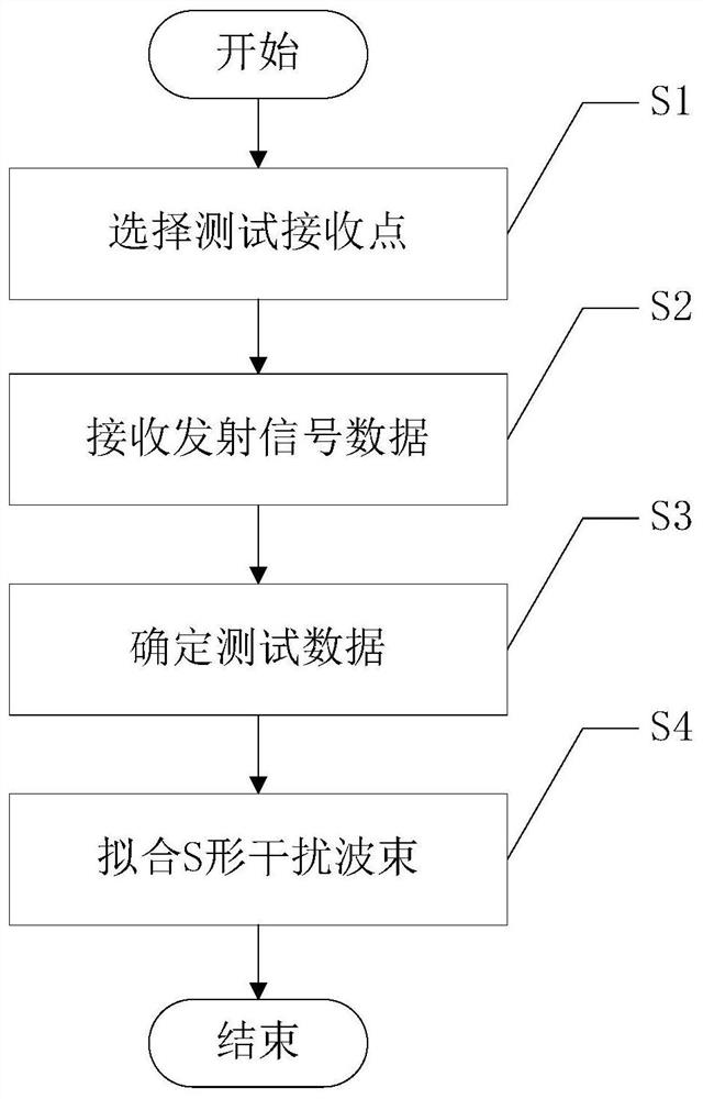
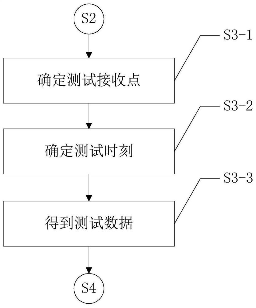
[0044] In the embodiment of the present invention, a method for testing an S-shaped interference beam based on a frequency-steered array, such as figure 1 shown, including the following steps:

[0045] S1: Select the test receiving point: According to the distribution position of the preset S-shaped interference beam of the frequency control array radar transmitter in space, select the placement point of the radar test rece...


PUM


Abstract

The invention discloses a method for testing S-shaped interference beams based on a frequency control array, comprising the following steps: S1. Selecting a radar test receiver according to the distribution position of a preset S-shaped interference beam in space of a frequency control array radar transmitter The placement point is the test receiving point; S2, make the frequency control array radar transmitter start to transmit signals, and make each test receiving point receive all the transmitted signal data of at least one preset transmission cycle through the test receiving point; S3 1. Determine the test data of each test receiving point according to the received transmission signal data; S4. According to the spatial position and test data of each test receiving point, draw the two-dimensional beam diagram of the frequency control array, that is, fit the S-shaped interference beam. The invention solves the problems of low practicability, low concealment, low test efficiency, high implementation cost and large capital investment existing in the prior art.

Description

technical field [0001] The invention belongs to the technical field of radar antennas, in particular to an S-shaped interference beam testing method based on a frequency control array. Background technique [0002] As a new type of radar technology, frequency control array radar applies the idea of ​​frequency diversity to array antennas, and obtains beam patterns related to distance, angle and time by increasing the frequency offset of each antenna, that is, frequency control array radar at a fixed time The beam pattern has distance and angle dependence. Traditional phased array beams cannot precisely interfere with irregularly distributed multi-targets. By utilizing the distance-dependent characteristics of the frequency-steered array two-dimensional beam pattern, the synthesized jamming beam with a specific shape can be used to jam multiple targets at the same time. [0003] The existing radar beam test is usually aimed at single antenna components. The conventional test...

Claims


Application Information

Patent Timeline
Patent Type & Authority Patents(China)
IPC IPC(8): G01S7/41G01S7/36G01S7/40
CPCG01S7/36G01S7/40G01S7/41
Inventor 陈慧贾文凯胡全王文钦邵怀宗潘晔廖轶
Owner UNIV OF ELECTRONICS SCI & TECH OF CHINA
Why Eureka
Try Eureka