
Method for testing frequency characteristic of front plate of fiber-optic gyroscope

A fiber optic gyroscope, frequency characteristic technology, applied in the direction of electronic circuit testing, etc., can solve the problems of slow measurement speed, unable to meet the fast and accurate measurement of the fiber optic gyroscope front board, and complicated operation.

Inactive Publication Date: 2013-11-27
ZHEJIANG UNIV
View PDF4 Cites 1 Cited by
  • Summary
  • Abstract
  • Description
  • Claims
  • Application Information

AI Technical Summary

Problems solved by technology

Therefore, how to quickly and accurately test the frequency characteristics of the fiber optic gyroscope preamplifier is a very important issue. The current frequency characteristic testing instruments have high cost, redundant functions, slow measurement speed, non-specialized instruments, complicated operation, and cannot test high The frequency characteristics under the high frequency can not be tested at any frequency point, which cannot meet the requirements of fast and accurate measurement of the frequency characteristics of the fiber optic gyro front board

Method used


Image

  • Method for testing frequency characteristic of front plate of fiber-optic gyroscope
  • Method for testing frequency characteristic of front plate of fiber-optic gyroscope
  • Method for testing frequency characteristic of front plate of fiber-optic gyroscope

Examples


Embodiment Construction

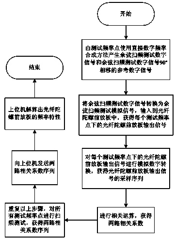
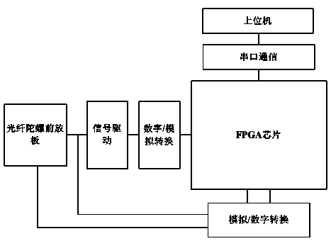
[0046] The present invention will be described in further detail below in conjunction with the accompanying drawings and specific embodiments.

[0047] Such as figure 1 Shown, the concrete steps of the inventive method are as follows:

[0048] 1) The test frequency point of the frequency characteristics of the fiber optic gyroscope front board to be tested is f i , where i=1,2,...,N, N is the number of frequency points to be tested, and each test frequency point f is preset i Corresponding to a frequency control word K i , according to the frequency control word K i Use the direct digital frequency synthesis method to obtain the frequency f i The cosine frequency sweep test digital signal and the cosine frequency sweep test digital signal 90° phase-shifted reference digital signal;

[0049] 2) The cosine frequency sweep test digital signal is successively converted into a cosine frequency sweep test analog signal through digital-to-analog conversion and signal drive, and ...


PUM


Abstract

The invention discloses a method for testing the frequency characteristic of a front plate of a fiber-optic gyroscope. The method includes the steps that a frequency control word corresponding to each testing frequency point is preset, cosine sweep check digital signals and reference digital signals are acquired by using a direct digital frequency synthetic method, wherein the reference digital signals are formed by conducting 90-degree phase shifting on the cosine sweep check digital signals, the cosine sweep check digital signals are converted into cosine sweep check analog signals and then input to the front plate of the fiber-optic gyroscope, analog digital conversion is conducted on output signals of the front plate of the fiber-optic gyroscope, and then the sample sequence of the output signals of the front plate of the fiber-optic gyroscope is acquired; two paths of correlation coefficients are acquired through correlation operations; all the testing frequency points are repeated to acquire the sequence of the two paths of correlation coefficients, and then the sequence is sent to an upper computer; parameters of the amplitude-frequency characteristic, parameters of the phase-frequency characteristic and parameters of the frequency characteristic of the front plate of the fiber-optic gyroscope are calculated and acquired. According to the method, the frequency characteristic of the front plate of the fiber-optic gyroscope can be rapidly and accurately measured, and the device utilizing the method has the advantages of being simple in structure, low in cost, high in measuring speed, large in measuring frequency range, and high in accuracy.

Description

technical field [0001] The invention relates to a method for testing frequency characteristics, in particular to a method for testing the frequency characteristics of an optical fiber gyroscope front board. Background technique [0002] Fiber optic gyroscope is a kind of fiber optic sensor sensitive to angular rate. The fiber optic gyro has the advantages of small size, light weight, wide range of accuracy, and no moving parts. It is a new type of all-solid-state inertial instrument. Due to the importance of the fiber optic gyroscope in the application fields of aviation, aerospace, navigation and weapons, it has received close attention from research institutions around the world from the very beginning, and has developed rapidly, becoming one of the mainstream instruments in the field of inertial measurement and guidance. [0003] The fiber optic gyroscope has two working modes, which are open-loop operation mode and closed-loop operation mode. The fiber optic gyroscope ...

Claims


Application Information

Patent Timeline
IPC IPC(8): G01R31/28
Inventor 李阳刘承陈杏藩
Owner ZHEJIANG UNIV
Learn More