

Gas pressure rapid measuring device and measuring method
A rapid measurement and gas pressure technology, applied in mining equipment, earth-moving drilling, mining equipment, etc., can solve the problems of long measurement period and gas leakage in the drilling and crushing circle, and achieve the effect of reduced time and easy operation.
- Summary
- Abstract
- Description
- Claims
- Application Information
AI Technical Summary
Problems solved by technology
Method used
Image

Examples
Embodiment 1
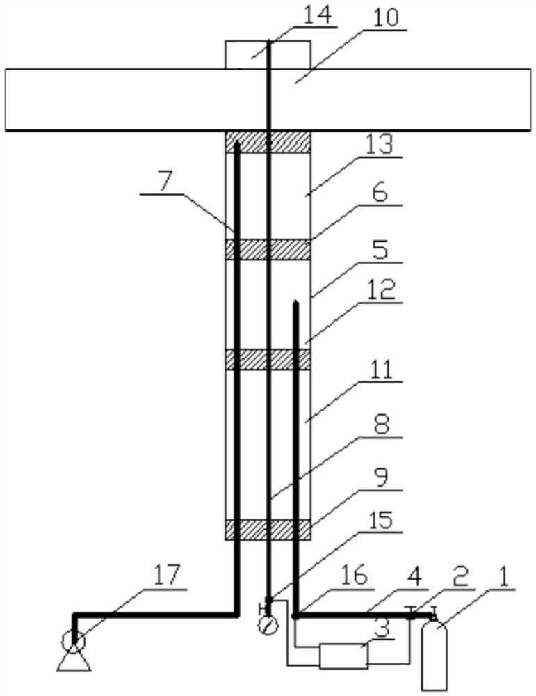
[0021] Such as figure 1 As shown, the gas pressure rapid measuring device in this embodiment is used to measure the gas pressure of the underground coal seam 10, and the underground construction faces the coal seam 10 direction to set up a borehole 5, and the back side of the coal seam provides a pressure measuring gas chamber 14, and the gas pressure rapid measuring device includes at least Four sealing capsules 6, gas injection device 1, gas injection tube 4, pressure measuring tube 8 and control device 3, wherein the sealing capsules 6 are arranged at intervals in the borehole 5, between two adjacent sealing capsules 6 Form the second sealing section 13, the gas injection space 12 and the first sealing section 11 which are sequentially arranged in the direction from the coal seam 10 to the opening of the borehole 5, and the first end of the pressure measuring tube 8 extends through the sealing capsule 6 and the coal seam 10 To the pressure measurement chamber 14, the second...
Embodiment 2
[0027] The gas pressure rapid measurement method uses the gas pressure rapid measurement device in Example 1.
[0028] A drilling rig is used to construct a borehole 5 with a corresponding aperture at a predetermined position, and the borehole 5 passes through the coal seam 10 or is constructed along the coal seam 10 . After the drilling 5 is completed, put the piezometric tube 8, the sealing capsule 6, and the liquid injection tube 7 into the specified position in the drilling 5, and use the liquid injection tube 7 to inject the sealing liquid 9 into the space between the capsule and the specified drilling 5 , Borehole 5 is blocked. The sealing capsules are divided into 6 and 4, and the borehole 5 is divided into a pressure measuring chamber 14, a second sealing section 13, an air injection space 12, and a first sealing section 11 from the inside to the outside. After the hole is sealed, the control device 3 is opened to monitor the gas pressure P1 of the coal seam 10 in the...
PUM
 Abstract
Description
Claims
Application Information