

OFDM signal transmission system, portable terminal, and e-commerce system
a transmission system and signal technology, applied in the field of transmission systems of signal, can solve the problems of reducing transmission capacity, increasing redundant time, and quick response to user demand, and achieve the effect of simple configuration
- Summary
- Abstract
- Description
- Claims
- Application Information
AI Technical Summary
Benefits of technology
Problems solved by technology
Method used
Image

Examples
first embodiment
(1) First Embodiment
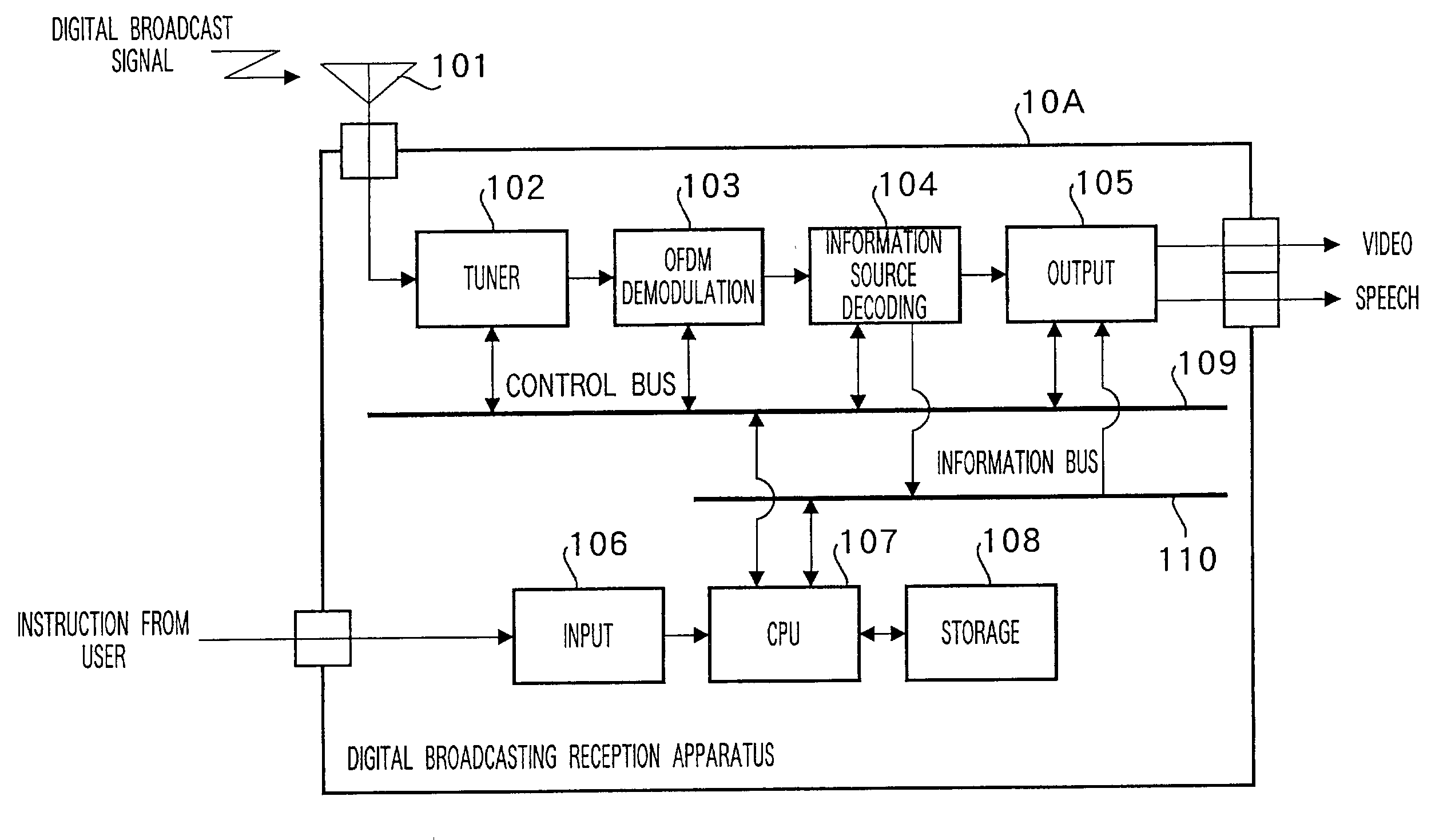
[0106]FIG. 5 is a block diagram showing a configuration of digital broadcasting reception apparatus 10A according to a first embodiment of the present invention.
[0107]This embodiment assumes a use mainly in a fixed reception environment such as household when the transmission mode does not change in a short time such as a program unit though the transmission mode may vary depending on the region or broadcaster, etc.
[0108]In FIG. 5, antenna 101 supplies a digital broadcast signal to an input of tuner 102. This tuner 102 selects a signal of a channel of the user's choice from the digital broadcast signal supplied from antenna 101, converts the frequency of the signal from a radio frequency band to a base frequency band and supplies the output to an input of OFDM demodulation section 103. OFDM demodulation section 103 applies processing such as demodulation and error correcting to the digital broadcast signal of the base frequency band to reproduce the transmission ...
second embodiment
(2) Second Embodiment
[0129]FIG. 10 is a block diagram showing a configuration of an OFDM signal transmission system according to a second embodiment of the present invention. In FIG. 10, components assigned the same reference numerals as those in FIG. 5 operate in the same way as in the first embodiment.
[0130]This embodiment assumes a use mainly in a mobile reception environment such as an automobile and cellular phone when the transmission mode does not change in a short time such as a program unit though the transmission mode may vary depending on the region or broadcaster, etc.
[0131]Furthermore, this embodiment operates in the same way as the first embodiment except that it identifies the current location using a Global Positioning System (hereinafter referred to as “GPS”).
[0132]In FIG. 10, GPS antenna 111 of digital broadcasting reception apparatus 10B supplies signals from GPS satellites 20A, 20B and 20C to an input of GPS processing section 112. GPS processing section 112 meas...
third embodiment
(3) Third Embodiment
[0134]FIG. 11 is a block diagram showing a configuration of an OFDM signal transmission system according to a third embodiment of the present invention. In FIG. 11, components assigned the same reference numerals as those in FIG. 5 operate in the same way as in the first embodiment.
[0135]This embodiment assumes a use mainly in a mobile reception environment such as an automobile and cellular phone as in the case of the second embodiment when the transmission mode does not change in a short time such as a program unit though the transmission mode may vary depending on the region or broadcaster, etc.
[0136]Furthermore, this embodiment operates in the same way as the first embodiment except that it identifies the current location using a position registration function in a cell-based mobile communication system.
[0137]The cell-based mobile communication system is a system whereby a service area is divided into multiple small areas called “cells”, a base station is pla...
PUM
| Property | Measurement | Unit |
|---|---|---|
| frequency band | aaaaa | aaaaa |
| frequency | aaaaa | aaaaa |
| resistance | aaaaa | aaaaa |
Abstract
Description
Claims
Application Information