Electronic safing system

a technology of electronic safing and circuit configuration, which is applied in the direction of vehicle registration/indication of working, process and machine control, vehicular safety arrangements, etc., can solve the problems of complex circuit configuration and higher cost, and achieve the effect of simple configuration, low cost and cost reduction

Inactive Publication Date: 2010-05-13
DENSO CORP
View PDF33 Cites 168 Cited by
  • Summary
  • Abstract
  • Description
  • Claims
  • Application Information

AI Technical Summary

Benefits of technology

[0005]In order to improve the reliability, the air bag system usually performs an on-board diagnosis. The on-board diagnosis diagnoses several parts of a circuit after the system is turned on. For example, as shown in FIG. 2, in a case that the reference voltage is set by a voltage divider circuit A, the reference voltage is changed by changing a voltage dividing ratio by using the resistance R1 and a switching element SW1. Then, the device diagnoses the comparator CP1 by monitoring the output of the comparator CP1 which is expected to be responsive to the reference voltage intentionally changed. However, a circuit B for changing the voltage dividing ratio is necessary. Therefore, a circuit configuration is complicated and needs a higher cost.
[0008]It is another object of the present invention to provide an electronic safing system which enables a diagnosis with simple configuration.
[0009]It is a still another object of the present invention to provide an electronic safing system which enables a diagnosis with low cost.
[0010]According to the present invention, an electronic safing system comprises a safing sensor which detects a physical quantity responsive to a collision of a vehicle and outputs a voltage signal according to a detected result. The electronic safing system further comprises a comparing circuit which compares the voltage signal from the safing sensor with a reference voltage and outputs a signal corresponding to the comparison result, and a microcomputer which determines whether a collision occurs or not based on the output voltage of the safing sensor and the output of the comparing circuit. The safing sensor has an output terminal which is connected to an input terminal of the comparing circuit. The microcomputer has a programmable analog I / O port which is connected to a built-in AD-DA converter and can be switched to an analog input port and an analog output port in a selectable manner according to an internal register. The programmable analog I / O port is connected with the input terminal of the comparing circuit. The microcomputer switches the programmable analog I / O port to the analog output port and outputs a predetermined voltage when diagnosing the comparing circuit, and diagnoses the comparing circuit by monitoring the output of the comparing circuit. According to the present invention, a diagnosis for the comparing circuit can be performed by using the programmable analog I / O port equipped on the micro computer. Therefore, it is possible to perform the diagnosis for the comparing circuit with simple circuit configuration. It is possible to eliminate additional circuit components which are assembled for the diagnosis purpose only. In addition, it is possible to reduce cost.

Problems solved by technology

Therefore, a circuit configuration is complicated and needs a higher cost.

Method used


Image

  • Electronic safing system
  • Electronic safing system
  • Electronic safing system

Examples


Embodiment Construction

[0014]An embodiment of the present invention is explained in detail while referring to the attached drawings.

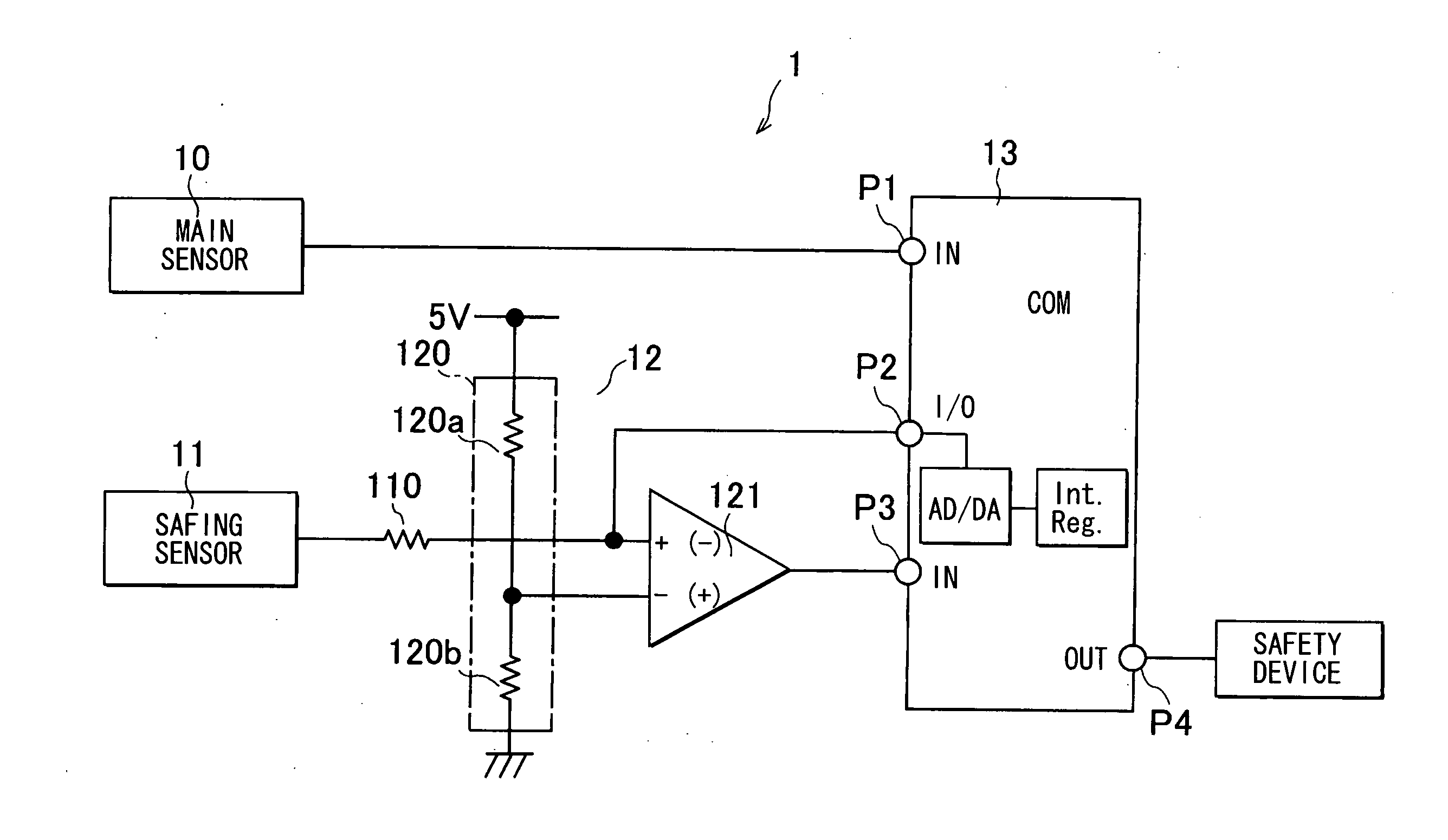
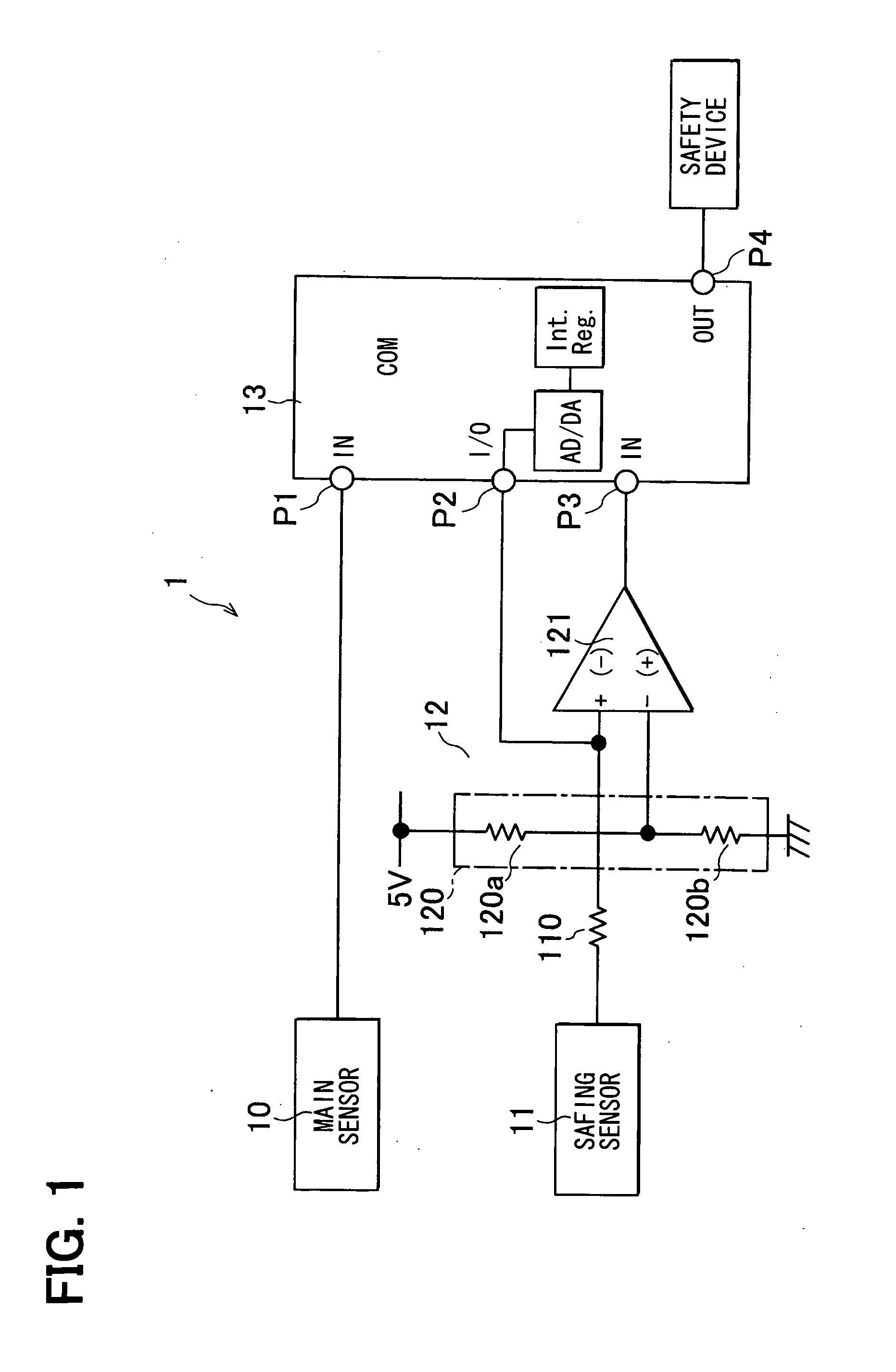
[0015]FIG. 1 shows a block diagram of an electronic safing system 1 according to the embodiment.

[0016]The electronic safing system includes a microcomputer which provides a verifying device. The verifying device verifies conditions of a circuit for processing an output signal from a sensor for detecting an event on a vehicle. The verifying device supplies a signal which imitates the signal of the sensor to the circuit while inhibiting a sensor responsive function of the system. The verifying device monitors an output from the circuit to determine whether the output is an expected signal or not. The electronic safing system may be called as a de-arming system for a vehicle occupant protection device. The system may include a main sensor and a sub sensor both of which detect the same event on the vehicle in the same or different ways. The sub sensor and its circuit are used for...


PUM


Abstract

The electronic safing system is provided with a safing sensor, a comparator, and a microcomputer. The microcomputer has a programmable analog I / O port which is connected to a built-in AD-DA converter. The programmable analog I / O port can be switched to an analog input port and an analog output port according to an internal register. The programmable analog I / O port is connected to an input terminal of the comparator. When diagnosing the comparing circuit, the microcomputer switches the programmable analog I / O port to the analog output port and outputs a predetermined voltage for diagnosis. Then, the microcomputer diagnoses the comparing circuit by monitoring the output of the comparing circuit.

Description

CROSS REFERENCE TO RELATED APPLICATION[0001]This application is based on Japanese Patent Application No. 2008-289031 filed on Nov. 11, 2008, the contents of which are incorporated herein by reference in its entirety.FIELD OF THE INVENTION[0002]The present invention relates to an electronic safing system.BACKGROUND OF THE INVENTION[0003]An electronic safing system includes a verifying system which verifies conditions of a detecting component for detecting an event on a vehicle. For example, the electronic safing system verifies a detecting circuit by supplying a signal which imitates a detecting signal of a sensor and by monitoring an output from the detecting circuit to determine whether the output signal is an expected signal or not.[0004]Conventionally, an air bag system disclosed in the document US Patent Application Publication 2004 / 0160045A1 (JP-2004-243955A) is known as an apparatus which uses the electronic safing system. The air bag system includes a first acceleration senso...

Claims


Application Information

Patent Timeline
Patent Type & Authority Applications(United States)
IPC IPC(8): G06F7/00
CPCB60R2021/01027B60R21/01
Inventor KIRIBAYASHI, SHINICHI
Owner DENSO CORP
Why Eureka
Try Eureka