Dose setting mechanism

a technology of a setting mechanism and a charge transfer mechanism, which is applied in the direction of medical syringes, infusion syringes, intravenous devices, etc., can solve the problems of damage to the components of injection devices, and achieve the effect of reducing the charging force transfer

Active Publication Date: 2019-07-25
NORTON HEALTHCARE
View PDF0 Cites 2 Cited by
  • Summary
  • Abstract
  • Description
  • Claims
  • Application Information

AI Technical Summary

Benefits of technology

[0017]In an embodiment, the over-torque feature is capable of reducing the charg

Problems solved by technology

A disadvantage of this arrangement is that, should the user continue to attemp

Method used


Image

  • Dose setting mechanism
  • Dose setting mechanism
  • Dose setting mechanism

Examples


first example embodiment

Description of First Example Embodiment

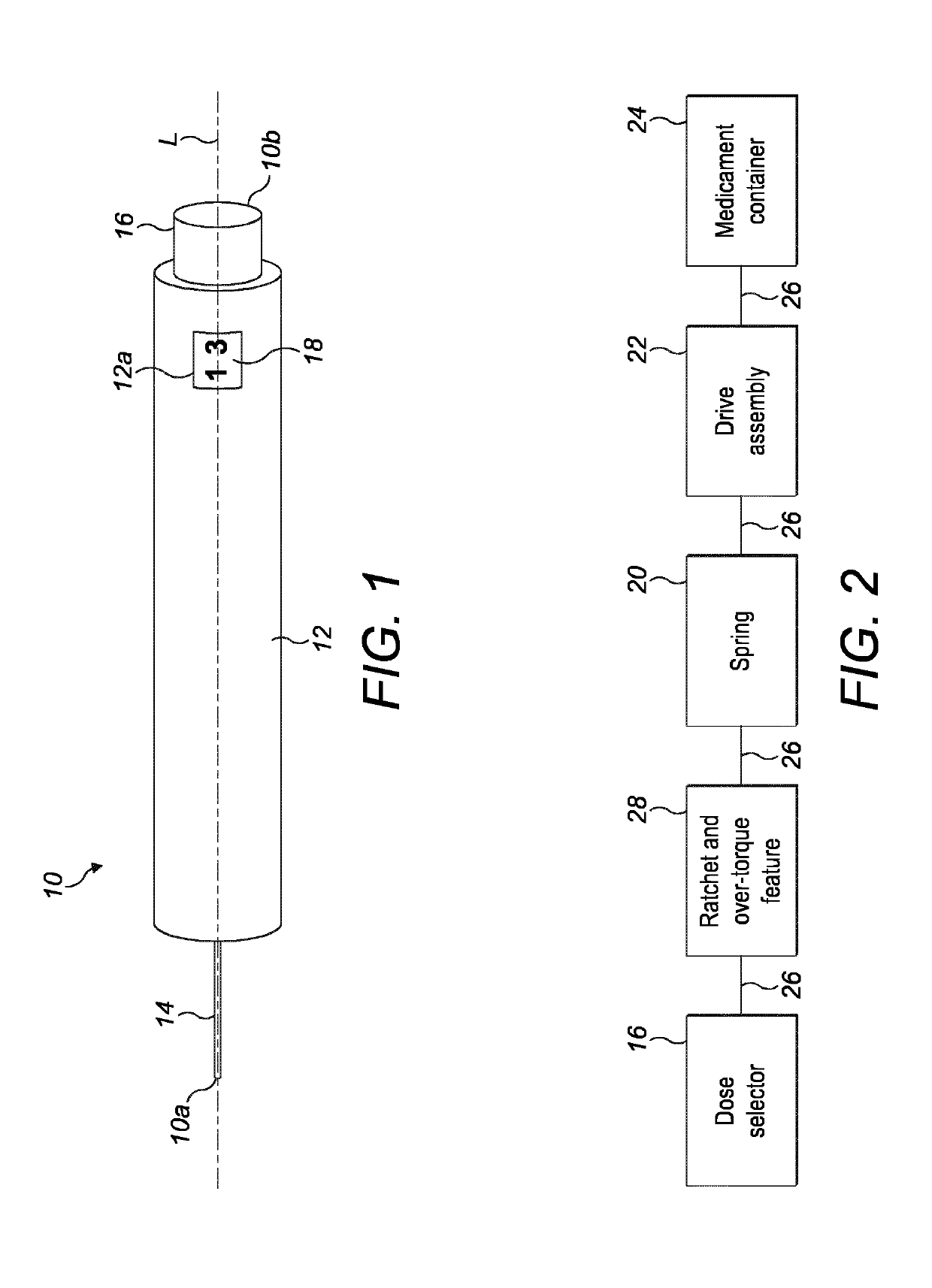
[0104]An injection device 10 according to an embodiment of the present invention is shown in FIG. 1. The injection device 10 is configured to deliver a dose of medicament and extends along a longitudinal axis L between a front end 10a and a rear end 10b of the injection device 10. The injection device 10 has a housing 12 and a needle 14 projecting from the housing 12 at the front end 10a. A dose selector 16 is provided at the rear end 10b and is arranged to permit the selection of a desired dose of medicament for delivery through the needle 14 into an injection site. The housing 12 includes an aperture 12a through which a dose indicator 18 is visible.

[0105]FIG. 2 shows a schematic representation of a force path 26 within the injection device 10. In particular, the force path 26 extends between internal components of the injection device 10 that are arranged in series with one another. The internal components include the dose selector 16, a ratc...

second example embodiment

Description of Second Example Embodiment

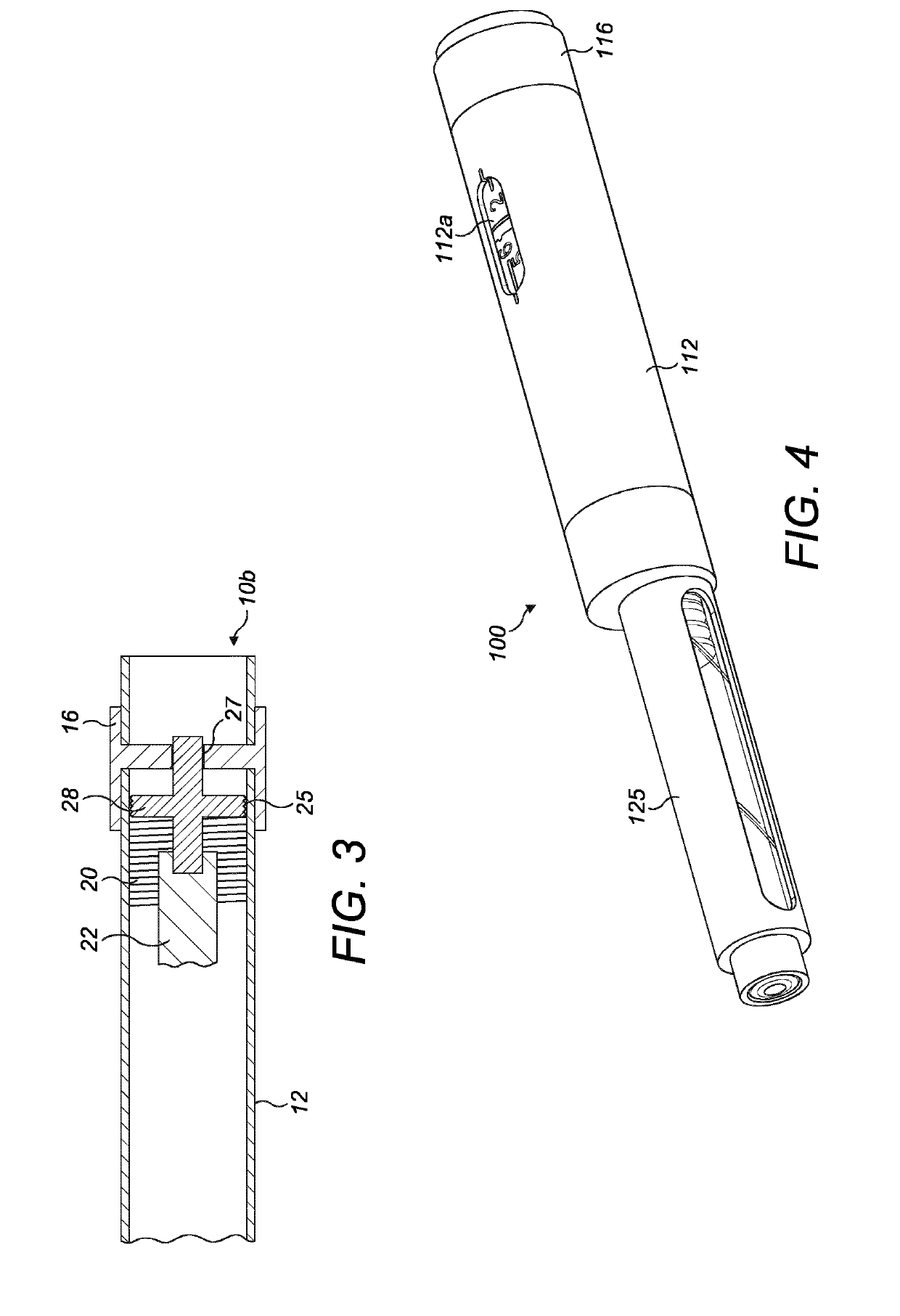
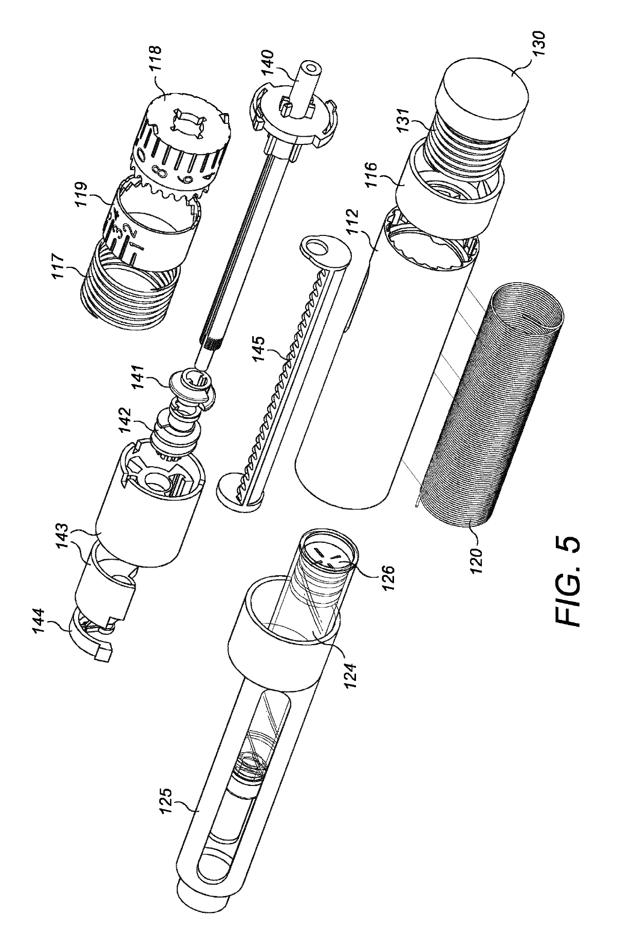
[0114]A further, non-limiting, embodiment of an injection device according to the present invention is illustrated in FIGS. 4-19B.

[0115]Referring to FIGS. 4-6, the injection device 100 includes a housing 112, a dose selector 116, a dose button 130 and dose button spring 131, a units wheel 118, a tens wheel 119, a dose indicator spring 117, a drive shaft 140, a drive spring 120, a dose limit nut 141, a worm gear 142, a worm gear support 143 and a worm gear rotational lock 144, all located concentrically about a common longitudinal axis L. The axis L extends between a front end 100a and a rear end 100b of the injection device 100.

[0116]The injection device 100 has a medicament cartridge 124 supported in a cartridge holder 125 at the front end 100a of the injection device 100. The cartridge 124 is sealed by an axially-moveable cartridge stopper 126 at its rear end. The cartridge and cartridge holder are located concentrically about a second longi...

third example embodiment

Description of Third Example Embodiment

[0158]A further, non-limiting, embodiment of an injection device according to the present invention is illustrated in FIGS. 20-40.

[0159]Referring to FIGS. 20-24, the injection device 200 includes a housing 212, a dose selector 216, a dose button 230 and dose button spring 231, a units wheel 218, a tens wheel 219, a ratchet pawl 217, a housing top cap 221, an odometer shuttle lock 222, a drive spring 220, a drive sleeve 240, a last dose nut 241, a drive clutch 250, a drive clutch spring 251, a leadscrew nut 252, a leadscrew 253 and a thrust bearing 254, all located concentrically about a common longitudinal axis L. The axis L extends between a front end 200a and a rear end 200b of the injection device 200.

[0160]The injection device 200 has a medicament cartridge 224 supported in a cartridge holder 225 at the front end 200a of the injection device. A needle or needle hub unit (not shown) can be connected to the cartridge holder. The cartridge is ...


PUM


Abstract

An injection device comprising a housing (12) and a dose selector (16) to set a dose of medicament to be ejected from the injection device. A spring (20) coupled to the dose selector stores energy necessary for ejecting the dose from the injection device. A ratchet (25) arrangement is provided to rotationally couple a ratchet component and an internal surface of the housing in a coupled state and to allow relative rotation between the ratchet component and the internal surface of the housing in an uncoupled state. An over-torque feature (27) located between the dose selector and the spring is actuatable, when the rotation of the dose selector causes the charging force to exceed a defined limit, to reduce the charging force transferred from the dose selector to the spring. Both the ratchet component and the over-torque feature are provided on a single component (28).

Description

[0001]This disclosure relates to the field of dose setting mechanisms for an injection device, preferably for reusable pen-type injection devices.BACKGROUND[0002]Certain injection devices have a dose setting member, or dose selector, via which the user can select a desired dose of medicament to be delivered from the injection device. The dose selector can commonly be actuated in one direction to increase the set dose (“dialling up”) and actuated in another direction to decrease the set dose (“dialling down”). As the dose is dialled up or down, this correspondingly increases or decreases stored energy in the device (e.g. in a torsion spring). An example of this type of dose setting can be seen in WO2006 / 045528.[0003]In WO2006 / 045528, a drive member is connected to a dose setting member via a self-tightening ratchet having saw-toothed teeth. The ratchet enables the dose setting member to be rotated in both directions so that a given dose may be set, whilst preventing the spring from u...

Claims


Application Information

Patent Timeline
IPC IPC(8): A61M5/20A61M5/315A61M5/24
CPCA61M5/20A61M5/2033A61M5/31553A61M5/24A61M5/31541A61M5/31593A61M2005/2093A61M2005/3126A61M5/3129A61M5/31511A61M5/31535A61M5/3157A61M5/31583
Inventor HEWSON, KARL JAMESBOSTOCK, GEORGESAVELL, GEORGE ROBERT MICHAELDAVIES, JAMES ALEXANDERHART, OLIVERSHENKER, JOSHUA ARIEHMORRIS, MATTHEW ALEXANDERFORDHAM, MATTHEW KEITH
Owner NORTON HEALTHCARE
Why Eureka
Try Eureka