Multi-use hammer device and method field of the invention

a multi-use, hammer technology, applied in the direction of screwdrivers, portable percussive tools, wrenches, etc., can solve the problems of inability to provide the directed force of pneumatic or hydraulic machines, unsuitable machines, and inability to straighten the vehicle body frame, etc., to achieve the accuracy of the angle at which the force is applied to a targeted object, and improve the accuracy of the effect of force application

Active Publication Date: 2015-07-02
ANEROB
View PDF13 Cites 5 Cited by
  • Summary
  • Abstract
  • Description
  • Claims
  • Application Information

AI Technical Summary

Benefits of technology

The use of the guide sleeve to guide the plunger greatly increases the accuracy at which a force is applied to a targeted object. Not only can the angle at which the force is applied be better controlled, but also the magnitude of the applied force as well. The guide sleeve acts as an alignment means for directing the force at a desired angle. Since the plunger travels along this aligned path, the angle at which the force is applied to a targeted object is very accurate. With a hammer and chisel, it is much more difficult to maintain this aligned path between the chisel axis and the angle at which the hammer strikes the chisel head; therefore, the angle at which force is applied to a targeted object is more inconsistent. In terms of force magnitude, the plunger may be slid within the guide sleeve at the appropriate velocity to increase or decrease the force transmitted through the impact head. The use of the guide sleeve in conjunction with the plunger also makes the application of force safer since there is no possibility that the plunger will become disengaged from or otherwise slip away from the impact head during impact. Since the plunger may be slid within the guide sleeve as opposed to being independently lifted or carried throughout a striking motion, the user must only overcome the slight friction between the guide sleeve and the plunger to move the plunger for contact with the impact head. The plunger may be lubricated as necessary to further reduce the amount of effort required to slide the plunger within the guide sleeve. The removable weights attached to the plunger can allow one to further vary the force applied. Additionally, the guide sleeve and plunger may be made longer or shorter depending upon the particular application and the amount of force to be applied to the targeted object. Because the impact head may be fitted with removable tips, the slide hammer is adaptable for use in many applications.
The impact head according to a preferred embodiment is housed within an impact head receiving section located at the distal end of the guide sleeve. The impact head receiving section may be removable from the guide sleeve which allows the impact head receiving section to be replaced with different sized impact heads. For example, the impact head receiving section may be threadably attached to the distal end of the guide sleeve. A removable impact head receiving section allows replacement of this section which undergoes greatest stress and strain during use, and therefore, potential damage over time.
A spring may be placed within the impact head receiving section to dampen contact between the plunger and the impact head, or alternatively, no spring may be used that allows the impact head to freely slide within the impact head receiving section. The advantage of using a spring within the impact head receiving section is that it helps stabilize the impact head prior to impact with the plunger; however, a disadvantage is that the force of the distal end of the plunger against the impact head is dampened thereby reducing transfer of force from the plunger to the impact head.
The use of the slide hammer of the present invention results in less force being transmitted back through the hands and arms of a user. When the plunger achieves the desired velocity within the guide sleeve, the user's hands need not be gripped so tightly around the proximal end of the plunger (as compared to a hammer and chisel) which, in turn, reduces the amount of force transmitted back through that hands and arms of the user. As discussed above with respect to a hammer and chisel, the hammer must always be tightly gripped during impact against the chisel which, in turn, results in much greater force being transmitted back through the hands and arms. Also, since the impact head is able to slide along a specified length within the guide sleeve, the guide sleeve itself may recoil and absorb retransmitted impact forces that further reduce the shock experienced by the user's hands and arms. In general, the sliding engagement of the impact head and the plunger within the guide sleeve combines to enhance the shock absorption characteristics of the slide hammer.
Since the impact head is able to slide with minimal resistance within the specified portion of the guide sleeve, the full impact of the moving plunger may be transmitted to the impact head which, in turn, helps to ensure that an adequate force is applied to the targeted object.

Problems solved by technology

However, even with the availability of such machines, it is still necessary in most cases to apply manual force to the frame in order to achieve the exact type of reshaping necessary to straighten the frame.
Particularly for hard-to-reach locations on the vehicle frame, pneumatic or hydraulic machines are simply not able to be positioned in a manner to provide the necessary directed force against a targeted frame location.
Also, for intricate reshaping of smaller frame members, machines are unsuitable.
Thus, the straightening of a vehicle body frame still requires a considerable amount of manual labor.
One disadvantage of using a hammer and chisel is that the hammer and chisel have to be firmly gripped, and when metal to metal contact is made between the frame and the chisel, most of the force of the impact is transmitted back through the user's hands and arms.
This force transmitted back through the hands and arms of a person can cause great pain and discomfort, as well as to cause premature fatigue.
Because the hammer has to be swung with such great force, the hammer itself can become a danger, particularly in hammering out hard-to-reach locations on the frame.
These and other known hazards make the use of a chisel and hammer undesirable.

Method used


Image

  • Multi-use hammer device and method field of the invention
  • Multi-use hammer device and method field of the invention
  • Multi-use hammer device and method field of the invention

Examples


Embodiment Construction

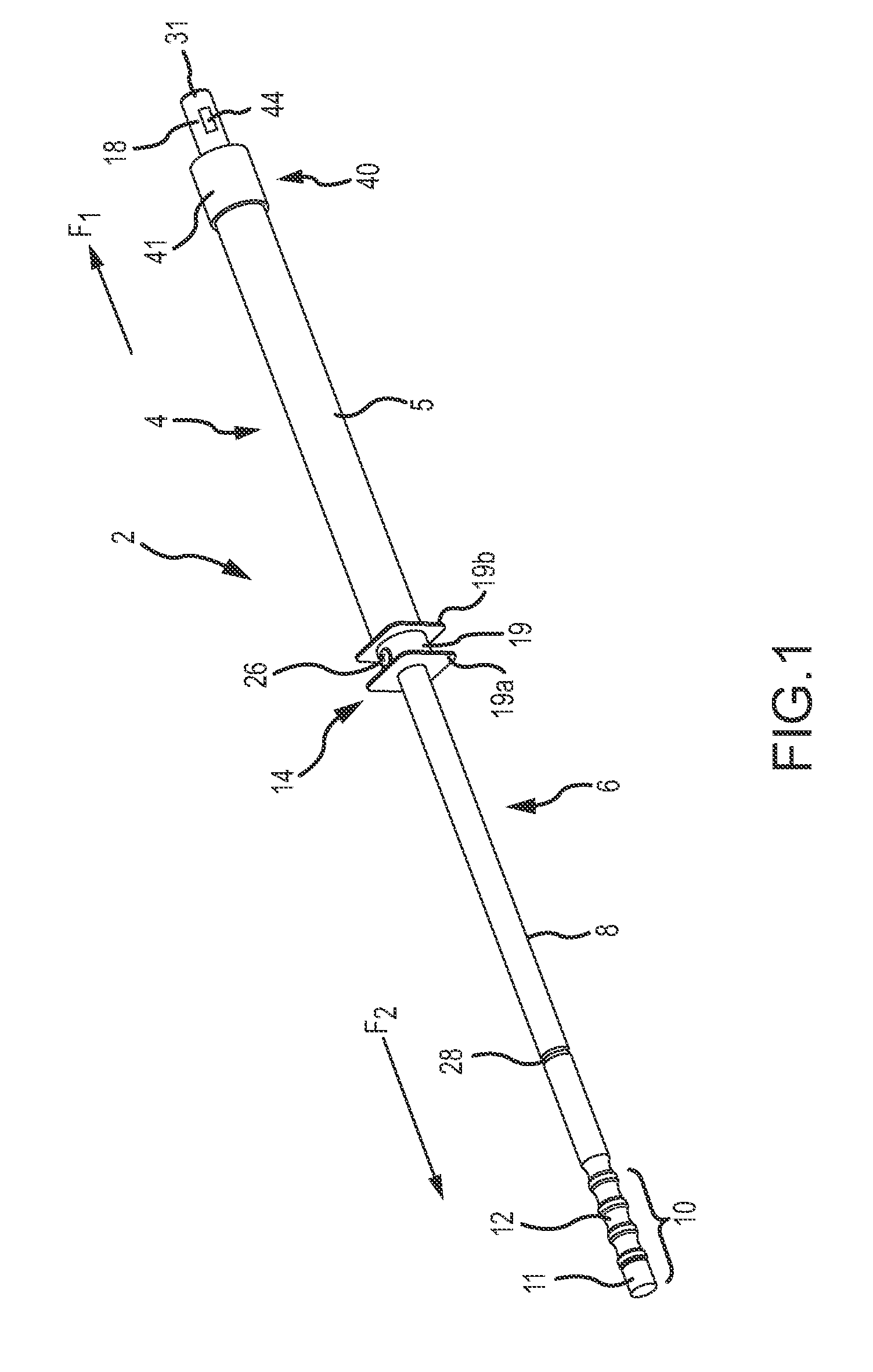
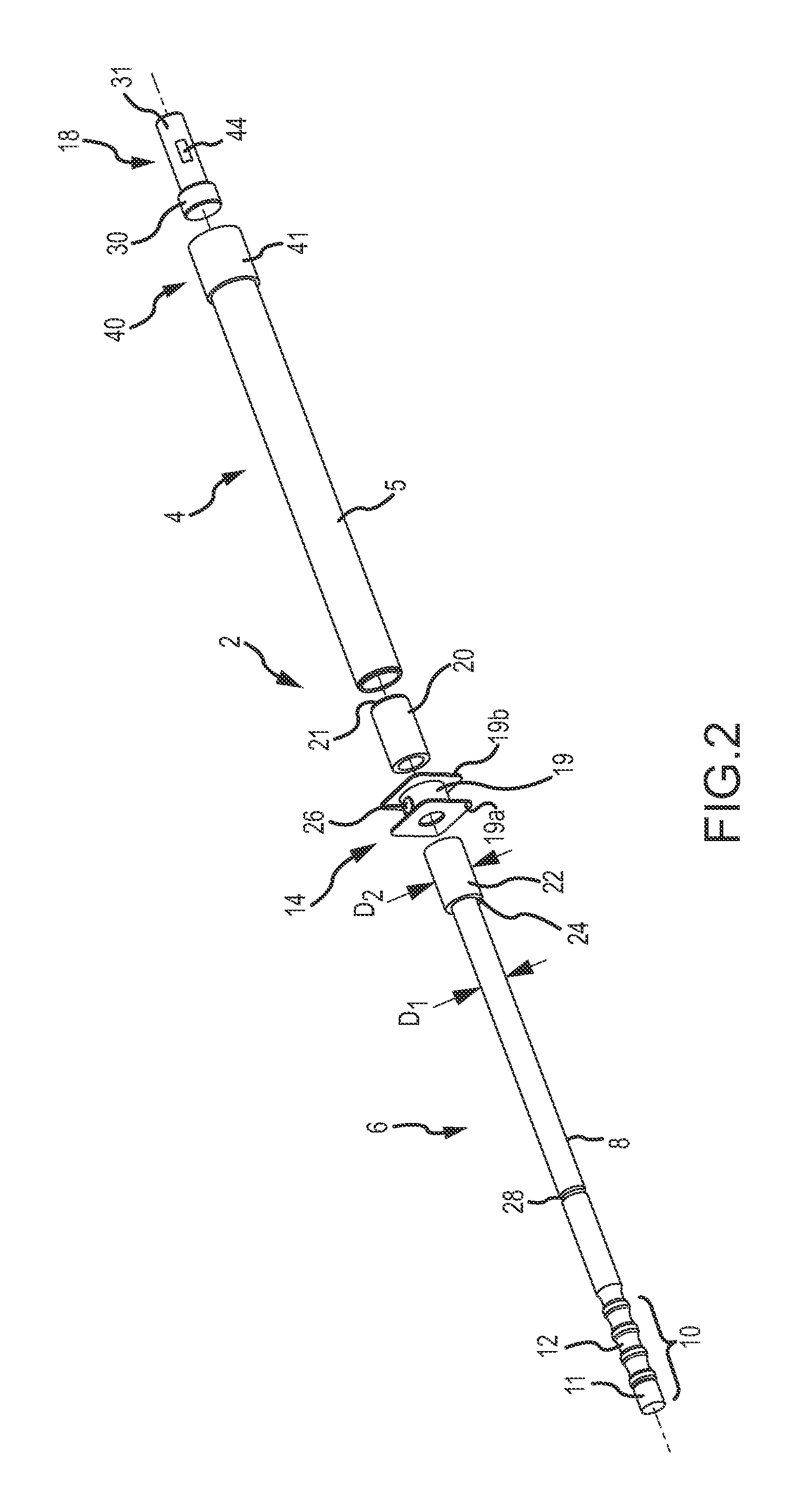
FIGS. 1-3 illustrate a slide hammer device according to a preferred embodiment of the invention. The slide hammer 2 comprises a guide sleeve 4 and a drive bar or plunger 6. In operation, the drive bar 6 is placed within the guide sleeve 4 and is slidable within at least a portion of a length of the guide sleeve 4. In the depicted embodiment, the drive bar 6 comprises a substantially cylindrical shaft portion 8, a user proximal portion 10, and an enlarged drive bar end 22. User portion 10 is grasped by the user, and may include features to enhance gripping, such as a hand-grip portion 12 and / or a knurled end portion. Other features placed on the user proximal portion 10 to enhance gripping for safety and functionality of the device 2 may include rubber grips or covers, enlarged and / or detachable handle portions, and finger or hand guard portions. When the device 2 is to be used as a pull hammer to generate tension / withdrawal forces, a flanged or bulbous feature may be threaded onto o...


PUM


Abstract

A slide and pull hammer device includes three major components, namely, a guide sleeve, a drive bar and an impact head. The drive bar is inserted within the guide sleeve. The impact head is secured within the distal end of the guide sleeve, and has a portion which protrudes beyond the guide sleeve distal end. The drive bar is operable to impact both a distal end and a proximal end of the guide sleeve to apply force to objects in at least two opposite force directions. One force applied by the device includes a hammering or compression force, and another force applied by the device includes a tension or withdrawing force.

Description

FIELD OF THE INVENTIONThis invention relates to a device that transfers the force of an impact to a targeted object and, more particularly, to a slide hammer that transfers the force of an impact to a targeted object, the force including either a hammering or compression force, or a tension or withdrawal force, depending upon the method in which the slide hammer is operated.BACKGROUND OF THE INVENTIONIt is known to use various combinations of chisels and hammers in order to impart a force upon a targeted object. In the automotive repair industry, it is often necessary to reshape and straighten vehicle body frames that have been damaged. Various forms of frame straightening machines are available for such purposes. However, even with the availability of such machines, it is still necessary in most cases to apply manual force to the frame in order to achieve the exact type of reshaping necessary to straighten the frame. Particularly for hard-to-reach locations on the vehicle frame, pn...

Claims


Application Information

Patent Timeline
Patent Type & Authority Applications(United States)
IPC IPC(8): B25D1/16
CPCB25D1/16B25B19/00B25D1/02B25D1/12B25D2250/171B25D2250/371
Inventor PATTERSON, R. J.
Owner ANEROB
Why Eureka
Try Eureka