Network system, layer 3 communication device, layer 2 communication device, and route selection method

a network system and communication device technology, applied in the field of network system, can solve the problems of network collapse, communication through the layer 2 network and communication is not performed on an optimum rou

Inactive Publication Date: 2011-07-19
FUJITSU LTD
View PDF61 Cites 26 Cited by
  • Summary
  • Abstract
  • Description
  • Claims
  • Application Information

AI Technical Summary

Problems solved by technology

This leads to a phenomenon called broadcast storm, in which a network collapses.
However, when part of the network is blocked, communication through the layer 2 network is not performed on an optimum route.
However, since communication between the IP networks 3000b and 3000c is performed on a route through the layer 2 switch 1000a, the communication is not performed on an optimum route.

Method used


Image

  • Network system, layer 3 communication device, layer 2 communication device, and route selection method
  • Network system, layer 3 communication device, layer 2 communication device, and route selection method
  • Network system, layer 3 communication device, layer 2 communication device, and route selection method

Examples


Embodiment Construction

[0030]Exemplary embodiments of the invention are explained in detail below with reference to the accompanying drawings.

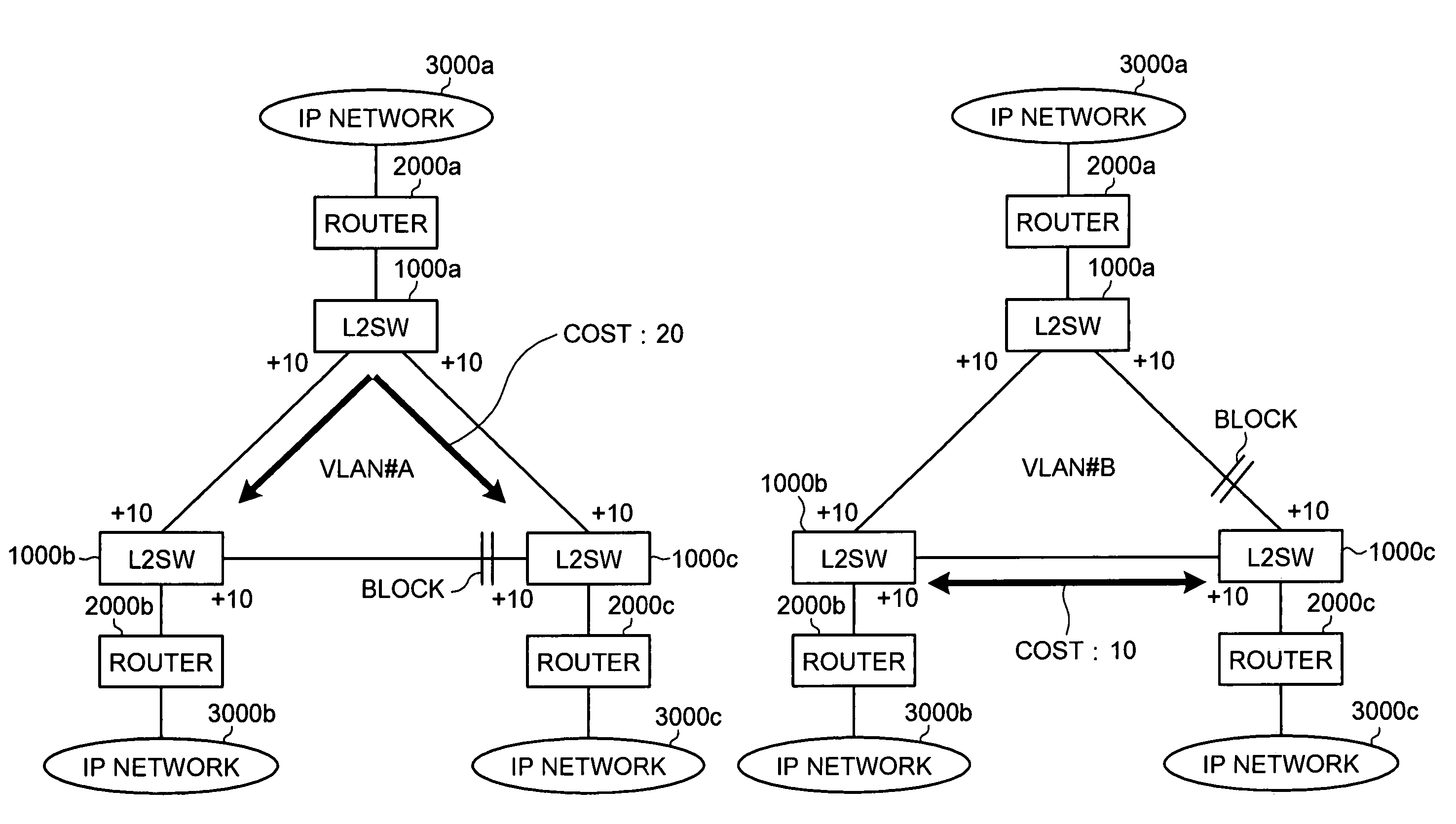
[0031]A route selection system according to an embodiment of the invention adopts a method of setting Virtual Local Area Networks (VLANs) among layer 2 networks to make the layer 2 networks multiple, and setting a block in a different position in each of the VLANs. This method can be realized by, for example, using a Multiple Spanning Tree Protocol (MSTP).

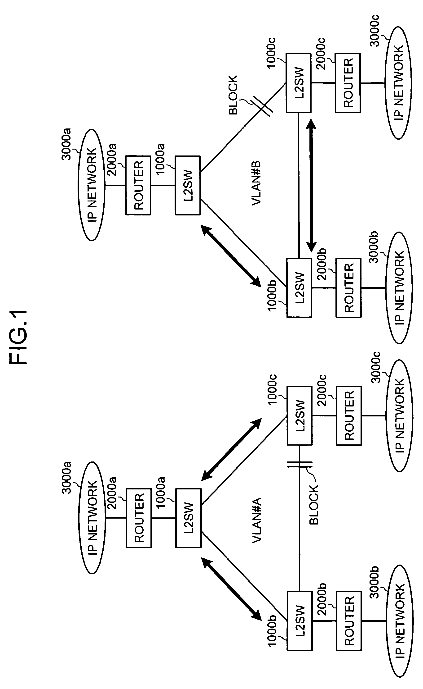
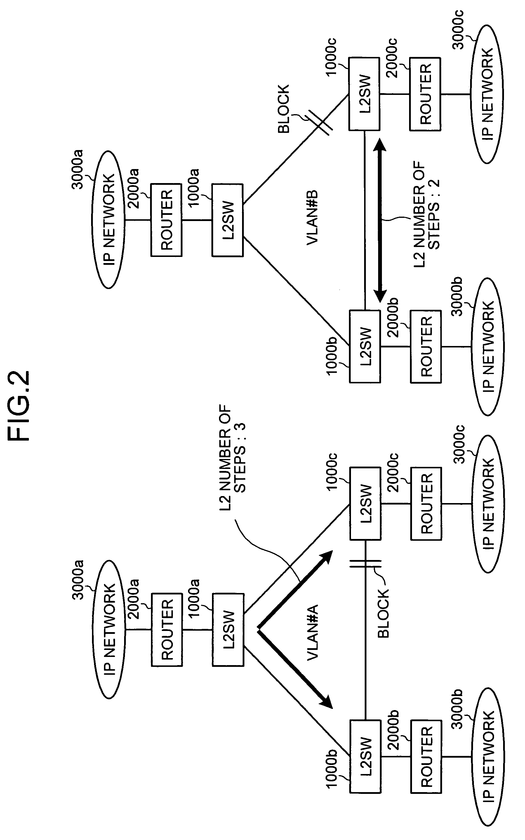
[0032]FIG. 1 is a diagram to explain a communication route in multiple layer 2 networks. In the figure, two VLANs, namely, a VLAN #A and a VLAN #B, are set in the layer 2 network of FIG. 13. In the VLAN #A, a block is set between the layer 2 switches 1000b and 1000c. In the VLAN #B, a block is set between the layer 2 switches 1000a and 1000c.

[0033]When communication is performed through the VLAN #A, communication between the IP networks 3000a and 3000b, and communication between the IP networks 3000a and 3000c are...


PUM


Abstract

In a layer 2 communication device included in multiple layer 2 networks, an identifying unit identifies a layer 3 control packet from among packets passing through, and an embedding unit embeds routing control information for the layer 2 network in the layer 3 control packet. In a layer 3 communication device connected to the multiple layer 2 networks, a selecting unit selects from the multiple layer 2 networks, an optimum L2 network, that is a layer 2 network forming an optimum communication route, based on a communication destination, and a setting unit sets a packet to be transmitted to the optimum L2 network.

Description

BACKGROUND OF THE INVENTION[0001]1. Field of the Invention[0002]The present invention relates to a network system, a layer 3 communication device, a layer 2 communication device, and a route selection method that make it possible to always select an optimum route for communication through a layer 2 network.[0003]2. Description of the Related Art[0004]In recent years, a large-scale network is often built as a layer 2 network because, for example, it is relatively inexpensive to install the layer 2 network. In building the layer 2 network, a loop of a packet occurs depending on a connection configuration of layer 2 switches (layer 2 communication devices). This leads to a phenomenon called broadcast storm, in which a network collapses.[0005]To avoid the broadcast storm, it is necessary to establish a connection form of the layer 2 switches in a tree structure physically or logically. In a system generally adopted, layer 2 switches are connected in a form of a mesh or a ring physically...

Claims


Application Information

Patent Timeline
Patent Type & Authority Patents(United States)
IPC IPC(8): H04L12/28H04L45/122H04L45/24
CPCH04L12/4641H04L45/28H04L49/602
Inventor HIROTA, MASAKI
Owner FUJITSU LTD
Why Eureka
Try Eureka