Techniques for routing data between network areas

a technology of routing data and network area, applied in the field of network communication, can solve the problems of increasing scale and managing, adding additional overhead and complexity, and significant problems and shortcomings associated with routing

Inactive Publication Date: 2012-09-13
RPX CLEARINGHOUSE
View PDF7 Cites 24 Cited by
  • Summary
  • Abstract
  • Description
  • Claims
  • Application Information

AI Technical Summary

Problems solved by technology

Such routing may be difficult to increase in scale and manage as the number of user VPNs increases.
Thus, this approach may also require external routing and may add additional overhead and complexity.
In view of the foregoing, it may be understood that there may be significant problems and shortcomings associated with current technologies for routing data between network areas.

Method used


Image

  • Techniques for routing data between network areas
  • Techniques for routing data between network areas
  • Techniques for routing data between network areas

Examples


Embodiment Construction

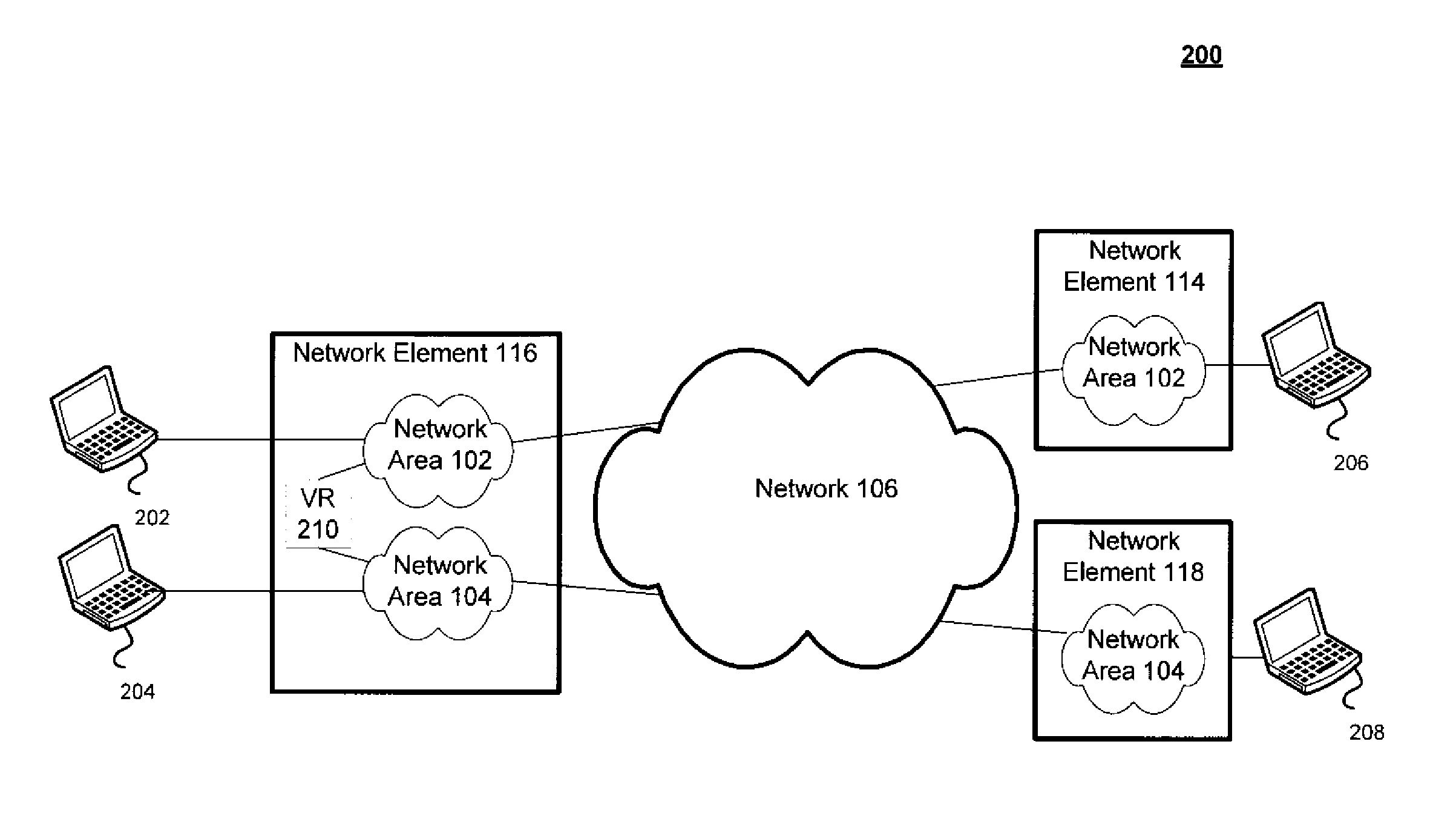
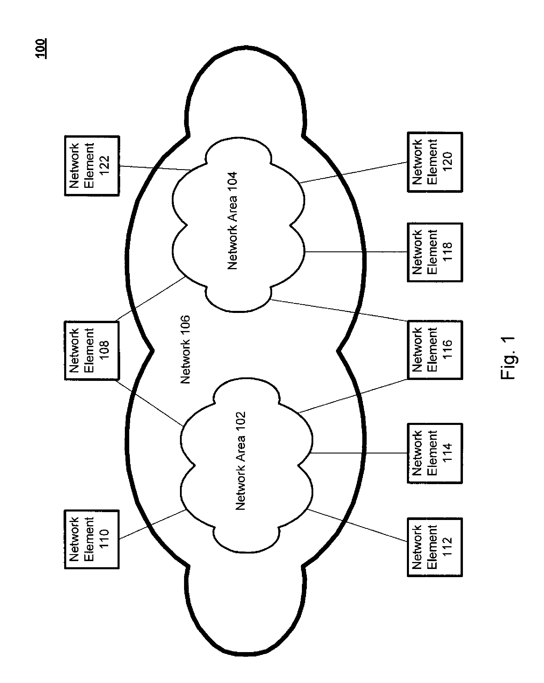
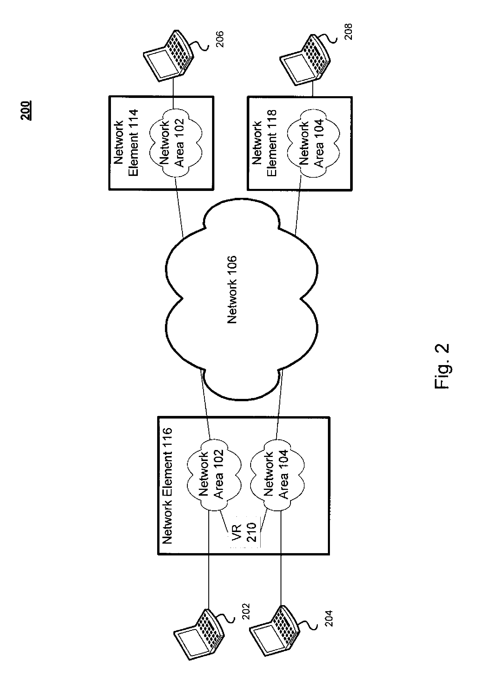
[0032]Referring to FIG. 1, there is shown a system 100 for routing data between network areas in accordance with an embodiment of the present disclosure. FIG. 1 is a simplified view of system 100, which may include additional elements that are not depicted. In system 100, network elements 108, 110, 112, 114, 116, 118, 120, and 122 may be communicatively coupled as part of network 106. Network 106 may be logically subdivided. For example, network 106 may be an IPv4 based network which may be subnetted into one or more areas or domains, such as network areas 102 and 104. Each of the network elements 108, 110, 112, 114, 116, 118, 120, and 122 may be communicatively coupled to one or more of the network areas 102 and 104. One or more of the network elements 108, 110, 112, 114, 116, 118, 120, and 122 may also be communicatively coupled to additional network areas (not shown). As illustrated, network elements 110, 112, and 114 may be communicatively coupled to network area 102. Network el...


PUM


Abstract

Techniques for routing data between network area are disclosed. In one particular exemplary embodiment, the techniques may be realized as a method for routing data between layer 2 network areas of backbone bridges comprising the steps of receiving data at a network element containing an internally terminated Network to Network Interface (NNI) for a plurality of network areas, identifying a destination address associated with the data, determining a network area of the plurality of network areas associated with the data, and performing one or more data flow treatments associated with the data using the internally terminated Network to Network Interface (NNI).

Description

CROSS-REFERENCE TO RELATED APPLICATIONS[0001]This patent application is a Continuation of U.S. patent application Ser. No. 12 / 483,690 filed Jun. 12, 2009, which is hereby incorporated by reference herein in its entirety.[0002]This patent application is related to U.S. patent application Ser. No. 11 / 899,118, filed Sep. 4, 2007, which is hereby incorporated by reference herein in its entirety.FIELD OF THE DISCLOSURE[0003]The present disclosure relates generally to network communications and, more particularly, to techniques for routing data between network areas.BACKGROUND OF THE DISCLOSURE[0004]Networks may be logically subdivided into Virtual Private Networks (VPNs), Virtual Local Area Networks (VLANs), or another logical subnets, network areas, or domains. For example, a VLAN may be further logically subdivided by a user into a plurality of user VLANs or VPNs. Provider Backbone Bridging (PBB) and / or Provider Link State Bridging (PLSB) may be used to separate an enterprise domain fr...

Claims


Application Information

Patent Timeline
Patent Type & Authority Applications(United States)
IPC IPC(8): G06F15/173
CPCH04L12/4625H04L45/66H04L45/04H04L12/4633H04L12/28H04L69/32
Inventor UNBEHAGEN, PAULLAPUH, ROGER
Owner RPX CLEARINGHOUSE
Why Eureka
Try Eureka