Many-for-one VLAN (Virtual Local Area Network) mapping chip realization method based on hardware study

An implementation method and many-to-one technology, applied in the field of network communication, can solve problems such as low network transmission efficiency, and achieve the effect of improving network transmission efficiency

Inactive Publication Date: 2016-05-04
SUZHOU CENTEC COMM CO LTD
View PDF7 Cites 0 Cited by
  • Summary
  • Abstract
  • Description
  • Claims
  • Application Information

AI Technical Summary

Problems solved by technology

[0004] The disadvantage of the N:1 VLAN mapping method mentioned above is that when returning from the NNI direction

Method used


Image

  • Many-for-one VLAN (Virtual Local Area Network) mapping chip realization method based on hardware study

Examples


Embodiment Construction

[0016] The technical solutions of the embodiments of the present invention will be clearly and completely described below in conjunction with the accompanying drawings of the present invention.

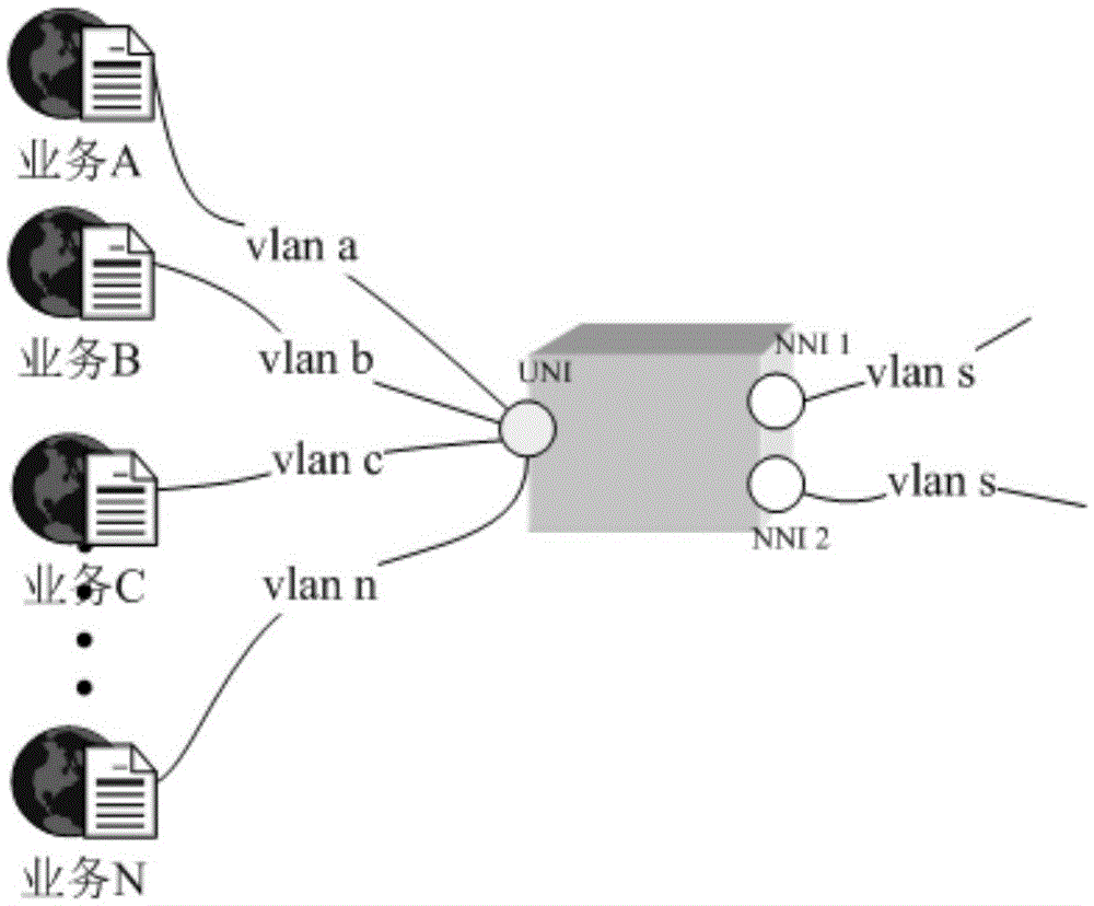
[0017] combine figure 1 As shown, a chip implementation method based on hardware learning of many-to-one VLAN mapping disclosed by the present invention, the method uses logical ports to distinguish different services, and uses logical ports to perform hardware learning and bind Nexthop for VLAN mapping, Realizing the N:1 VLAN mapping does not require multiple broadcasts when returning from the NNI direction to the UNI.

[0018] The specific implementation is as follows:

[0019] When multiple services exist on a port at the same time, different services can be distinguished through VLAN. Multiple services are forwarded between the UNI direction and the NNI direction at the same time, such as figure 1 . At this time, N VLANs (a, b, c...n) are simultaneously mapped to the same VLAN...


PUM


Abstract

The invention discloses a many-for-one VLAN mapping chip realization method based on hardware study. Different services are distinguished through using logic ports; the logic ports carry out hardware study and bind Nexthop for carrying out VLAN mapping; therefore, the many-for-one VLAN mapping is unnecessarily broadcasted for many times from a NNI (Network to Network Interface) direction to a UNI (User Networks Interface). The network transmission efficiency is greatly improved through the method.

Description

technical field [0001] The invention relates to the technical field of network communication, in particular to a chip implementation method of many-to-one VLAN mapping based on hardware learning. Background technique [0002] In the prior art, VLAN (VirtualLocalAreaNetwork Virtual Local Area Network) is to logically divide a physical local area network into multiple broadcast domains. Hosts in the same VLAN can communicate directly, but different VLANs cannot directly communicate with each other, thus broadcasting messages Restricted within a VLAN. Since different VLANs cannot directly communicate with each other, network security is improved. VLAN mapping is used to implement communication between different VLANs. After the message is received from the ingress port of the switch, when the frame of the local VLAN is sent out, the VLAN in the frame is replaced with the external VLAN. When receiving a frame of an external VLAN, replace the VLAN in the frame with a local VLA...

Claims


Application Information

Patent Timeline
IPC IPC(8): H04L12/46H04L12/24H04L29/12
CPCH04L12/4641H04L12/467H04L41/0806H04L2101/622
Inventor 何志川蒋华赵茂聪
Owner SUZHOU CENTEC COMM CO LTD
Why Eureka
Try Eureka