Arrangement for and method of providing cooling energy to a cooling medium circuit of a marine vessel

a cooling medium and marine technology, applied in the field of marine vessels, can solve the problems of consuming energy and work to be done, and achieve the effects of reducing total costs, saving fuel, and reducing electrical power

a cooling medium and marine technology, applied in the field of marine vessels, can solve the problems of consuming energy and work to be done, and achieve the effects of reducing total costs, saving fuel, and reducing electrical power

US8043136B2Active Publication Date: 2011-10-25WARTSILA FINLAND OY

Image

  • Arrangement for and method of providing cooling energy to a cooling medium circuit of a marine vessel
  • Arrangement for and method of providing cooling energy to a cooling medium circuit of a marine vessel
  • Arrangement for and method of providing cooling energy to a cooling medium circuit of a marine vessel

Examples


Embodiment Construction

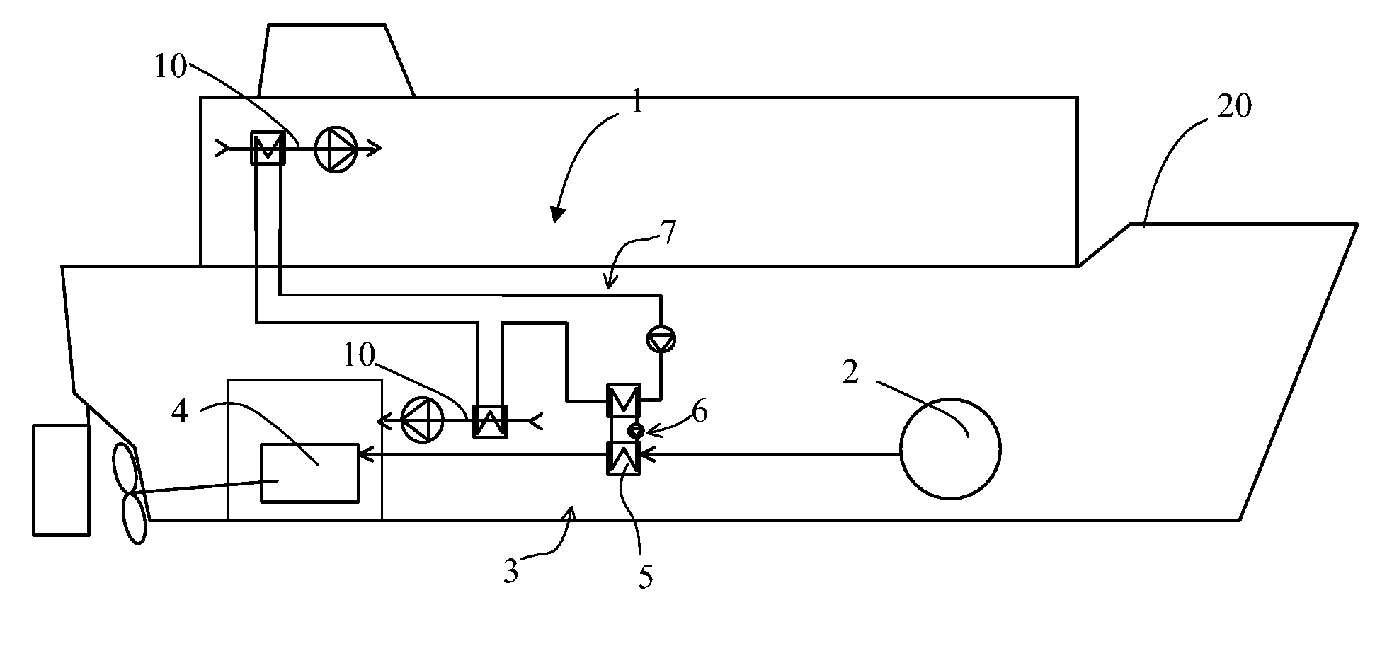
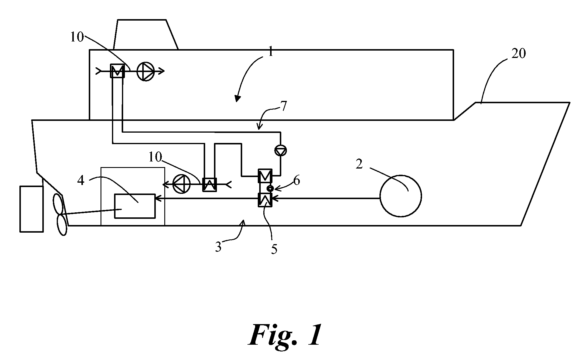
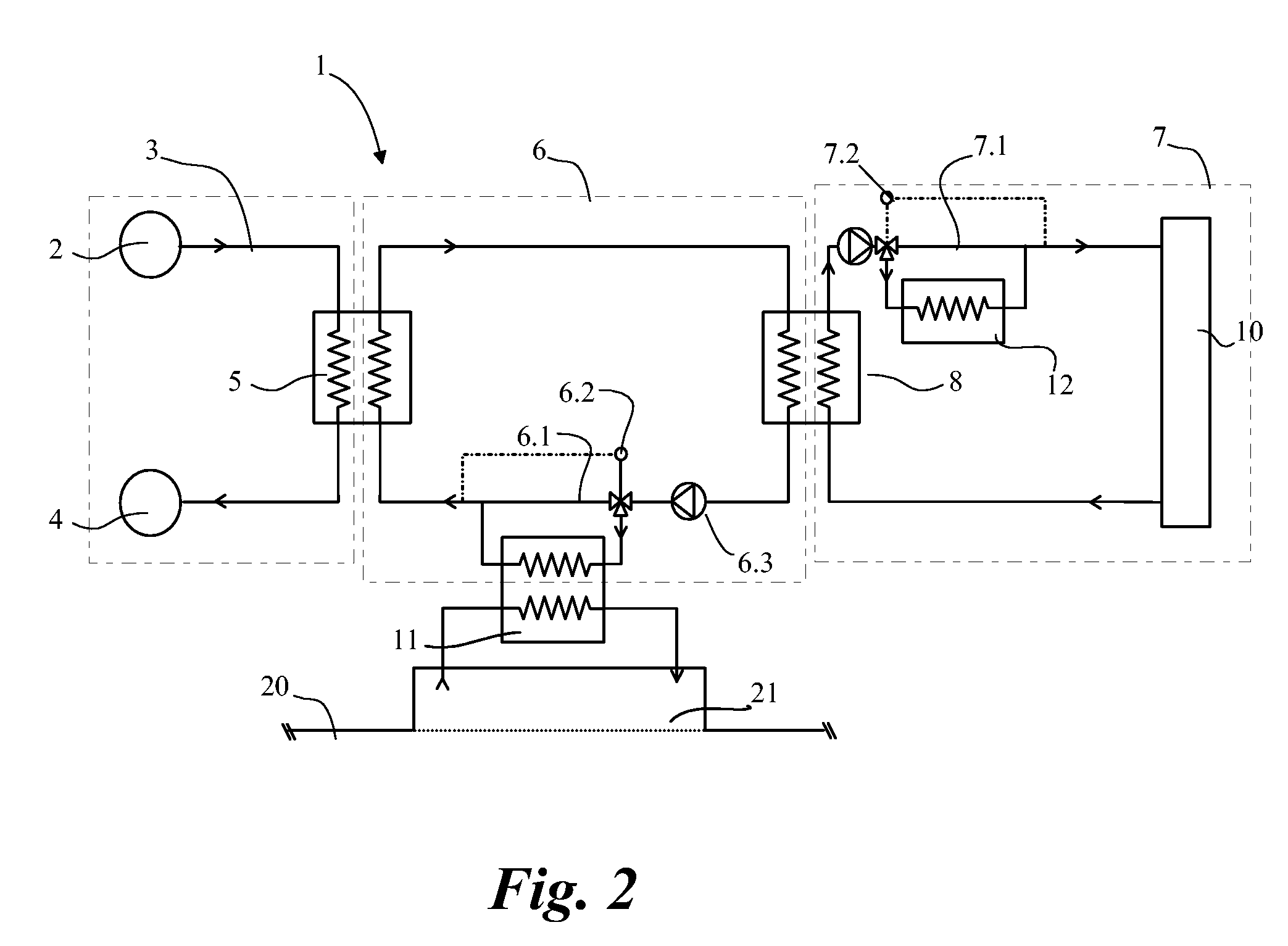
[0016]With the reference to FIGS. 1, 2 and 3 there is shown a marine vessel 20 operated by liquefied gas, like LNG, which is stored in a tank 2. In FIG. 1 there is shown a marine vessel 20 which has an engine of its propulsion system operated by gas. In this case the vessel is a passenger cruise vessel. Particularly in cruise vessels considerably much power is needed for cooling purposes and the cooling targets may be widely distributed in the vessel. The gas is stored in liquefied phase. The presentation of FIG. 1 is very schematic and only features necessary of understanding the context are shown. The description of embodiments of the invention is more accurately described with the reference to FIGS. 2 and 3.

[0017]Liquefied gas is stored typically at a temperature of −162° C. or somewhat higher temperature depending for example on the tank pressure. Before the gas may be introduced into the engine 4 of the vessel it must be evaporated into gaseous form and heated. For making that ...


PUM


Abstract

Arrangement for providing cooling energy to a cooling medium circuit of a marine vessel having a storage of liquefied gas, the arrangement having a gas feeding system being provided with gas evaporation / heating apparatus. The gas evaporation / heating apparatus is arranged in heat transfer connection with the cooling medium circuit of the vessel through an intermediate flow circuit.

Description

[0001]This is a national stage application filed under 35 USC 371 based on International Application No. PCT / FI2006 / 050425 filed Oct. 4, 2006, and claims priority under 35 USC 119 of Finnish Patent Application No. 20055707 filed Dec. 28, 2005.TECHNICAL FIELD[0002]The invention relates to marine vessels being operated with gaseous fuel. The invention particularly relates to an arrangement for providing cooling energy to a HVAC facility of a marine vessel having a storage of liquefied gas, the arrangement having a gas feeding system being provided with gas evaporation / heating apparatus. Invention relates also to a method of cooling a HVAC facility of a marine vessel having a storage of liquefied gas, in which method liquefied gas is evaporated and / or heated by a gas evaporation / heating apparatus.BACKGROUND ART[0003]In a marine vessel operated by using liquefied gas such as LNG (=Liquefied Natural Gas) the fuel is normally stored in tank approximately at a temperature of minus 162° C. ...

Claims


Application Information

Patent Timeline
25 Oct 2011
Publication
US8043136B2
IPC
F02B61/04; B63J2/00; B63J2/12; B63J2/14
CPC
B63J2/00; B63J2/14; B63J2/12; Y02T70/72; Y02T70/00; F17C9/02
Inventors
SIPILA, TUOMAS; LEVANDER, OSKAR