Sway brace

a sway brace and sway rod technology, applied in the direction of hose connection, instruments, signs, etc., can solve the problem that the sway brace is not necessarily contemplated for sustaining the full load of the pipe, and achieves less critical strength in the sway brace, increased strength in the same direction, and substantial rigidity.

Active Publication Date: 2011-12-06
ASC ENGINEERED SOLUTIONS LLC
View PDF43 Cites 22 Cited by
  • Summary
  • Abstract
  • Description
  • Claims
  • Application Information

AI Technical Summary

Benefits of technology

[0005]Heretofore, metal strapping has been employed in a U-shaped curve about an axis parallel to the width direction of the strapping to receive the pipe or conduit. In the present instance, the strapping is arranged to present one thin side, or thickness, to the pipe or conduit with the width direction of the strapping extending radially from the pipe or conduit. With this orientation of the strapping, the brace provides substantial rigidity against lateral motion of the pipe or conduit. Strength in the same direction is also increased. Longitudinally of the pipe or conduit, strength in the sway brace is less critical as longitudinal sliding may even occur. At the same time, mounting fixtures from the devices of the two aforementioned Kirschner applications are compatible and the straps can be of the same material, albeit, distinctively formed.

Problems solved by technology

Such bracing is not necessarily contemplated for sustaining the full load of the pipe during normal operation.

Method used


Image

  • Sway brace
  • Sway brace

Examples


Embodiment Construction

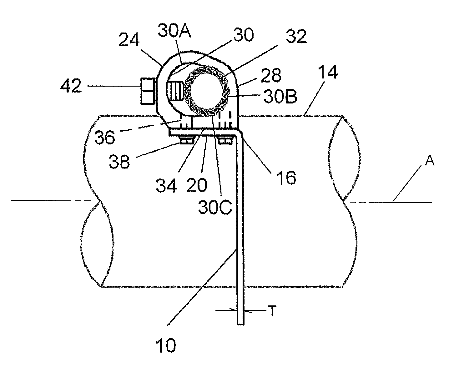
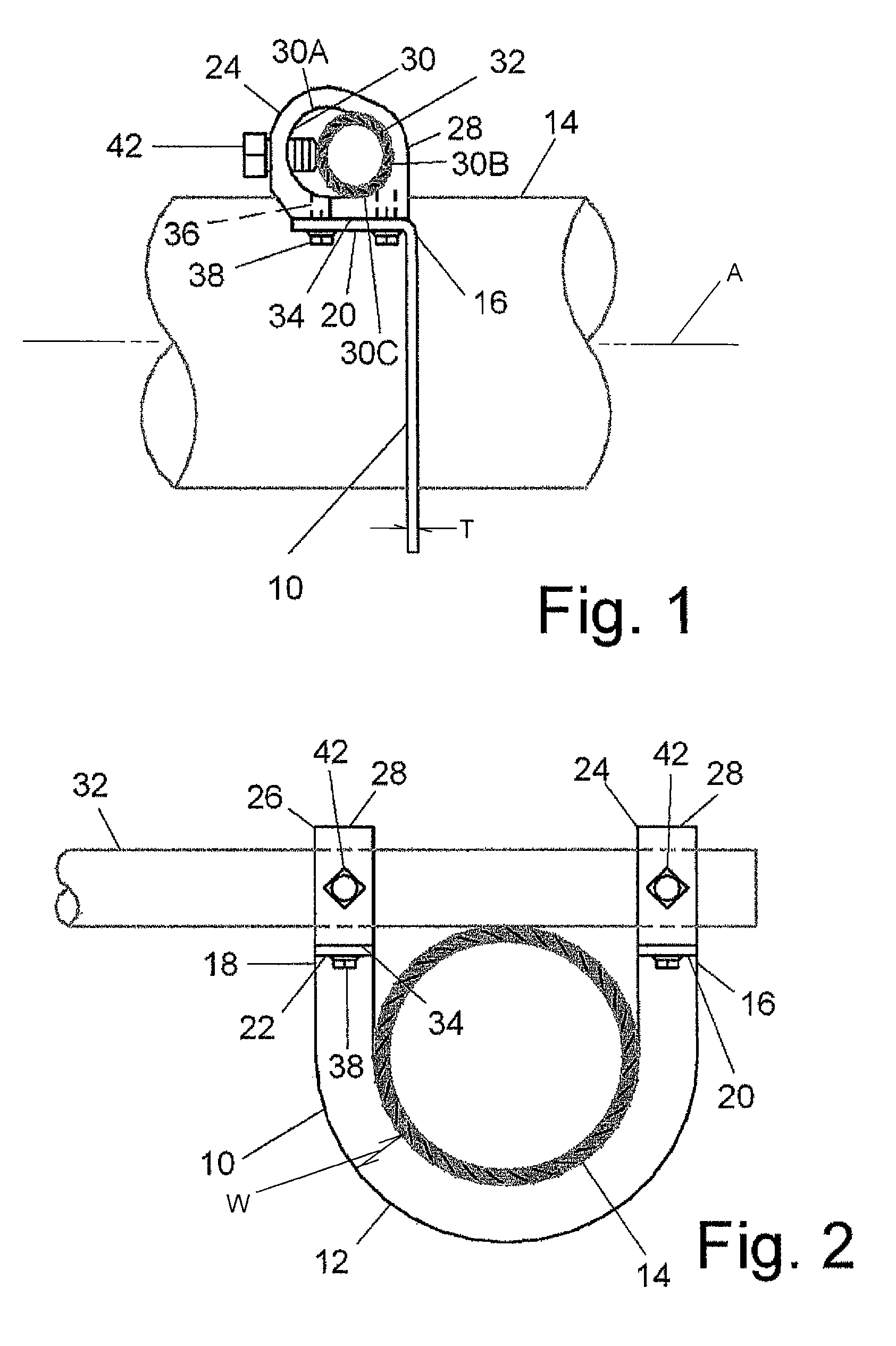
[0009]The Figures illustrate a sway brace including a sling 10. The sling 10 contemplates a specific diameter of pipe to be retained therein. Further, the pipe or conduit is not supported by the sling 10 such that the sling 10 would conform to a constant load. The sling 10 is defined by metal strapping formed in a U-shaped curve 12 about an axis A which is perpendicular to the width direction W of the strapping. Thus, the strapping extends radially in the width direction W from the pipe or conduit 14. The sling 10 is thus configured to receive the pipe or conduit 14 bearing against the thickness direction T of the strapping. The axis A about which the U-shaped curve is formed roughly corresponds to the centerline of the pipe or conduit 14 contemplated to be supported by the sway brace.

[0010]The strapping is preferably of commonly available materials of a strength to conform to building standards. Conveniently it may be of the same material contemplated for use in the aforementioned ...


PUM


Abstract

A sway brace including a U-shaped sling with flanges at each end. The flanges are mounted to two mounting fixtures including block bodies and passages therethrough. Mounting surfaces on the fixtures receive the flanges of the U-shaped sling. Threaded members affix the flanges to the mounting surfaces of the mounting fixtures. The sling includes metal strapping formed in a U-shaped curve about an axis perpendicular to the width of the strapping in a manner to create rigidity and strength.

Description

BACKGROUND OF THE INVENTION[0001]The field of the present invention is bracing for preventing pipes from swaying relative to an associated building structure.[0002]Building codes, as well as competent construction practice, require the securing of fluid lines and other utilities to the structure of a building to brace such lines against damaging movement resulting from seismic disturbances. Sway braces have been designed for securing numerous types of pipes and conduits. An example of such secured lines is fire control water sprinkler distribution pipes. When sprinkler systems are used in buildings, it is required that the water distribution pipes be adequately braced so that, in the event of an earthquake, the pipes will not unduly sway relative to adjacent portions of the building and separate or produce excessive leakage at the pipe joints. Such bracing is not necessarily contemplated for sustaining the full load of the pipe during normal operation. Indeed, the sway brace may act...

Claims


Application Information

Patent Timeline
Patent Type & Authority Patents(United States)
IPC IPC(8): F16L3/08
CPCA62C35/68F16L3/085F16L3/1207F16L3/24Y10T24/318Y10T24/31Y10T24/1412F16L3/245
Inventor KIRSCHNER, KRAIG A.
Owner ASC ENGINEERED SOLUTIONS LLC
Why Eureka
Try Eureka