Cosmetic Product Distributor-Applicator

Inactive Publication Date: 2007-05-03
ALCAN PACKAGING BEAUTY SERVICES
View PDF2 Cites 14 Cited by
  • Summary
  • Abstract
  • Description
  • Claims
  • Application Information

AI Technical Summary

Benefits of technology

[0006] It is characterised in that said body includes a device capable of generating vibrations, typically periodic vibrations, said device including a vibration generator, for example and electrical vibrator, a power source, constituted for example by an electric battery, and an associated electric circuit for supplying power to said vibration generator, and means for starting and stopping said vibration generator, typically a switch of said electric circuit, so that, during said application of said product on said support, said application means can produce in particular a massaging effect on said support, said vibration generator being activated during all or part of said application.
[0007] The distributor-applicator solves the stated problems. First, the vibrations emitted by the vibration generator are necessarily transmitted to the product contained in said container, which thereby enables the flow and application of a product that, in

Problems solved by technology

First, the vibrations emitted by the vibration generator are necessarily transmitted to the product contained in said container, which thereby enables the flow and application

Method used


Image

  • Cosmetic Product Distributor-Applicator
  • Cosmetic Product Distributor-Applicator
  • Cosmetic Product Distributor-Applicator

Examples


example 1

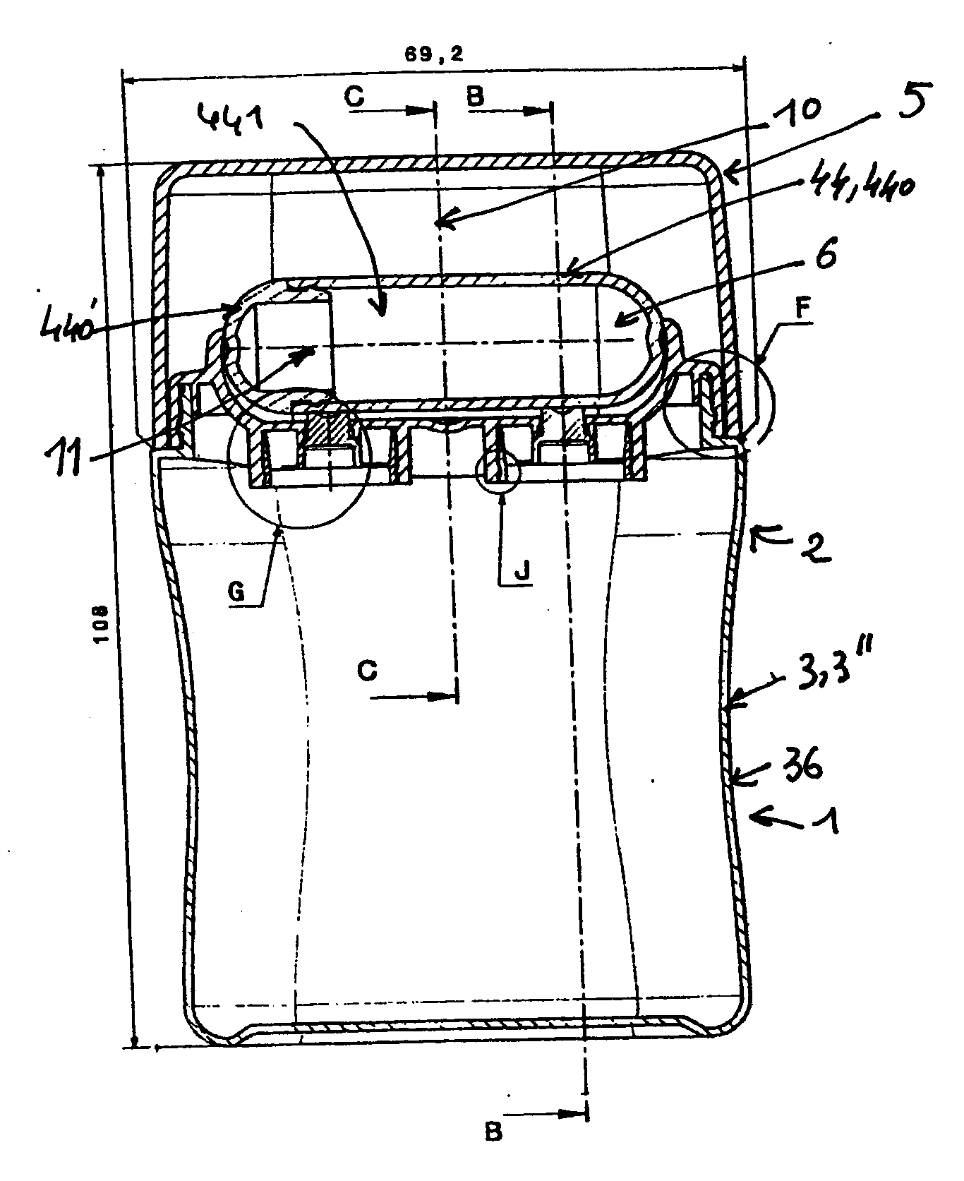
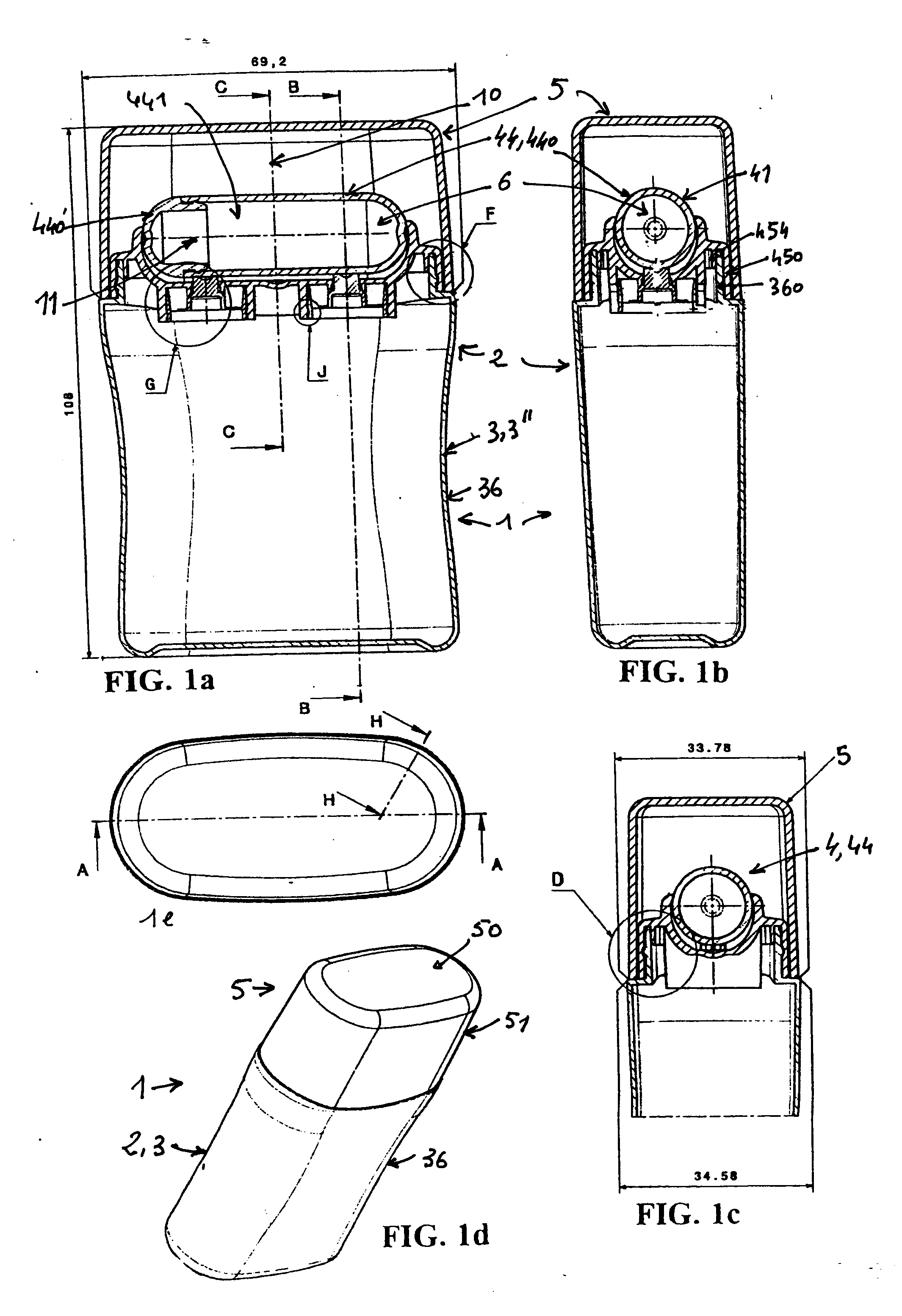
[0104] This example describes producing the distributor-applicator 1 according to FIGS. 1a to 7d.

[0105] To do this, the following parts were molded with plastic material or were supplied:

[0106] a container 3, 3″ according to the drawings of FIGS. 5a to 5g;

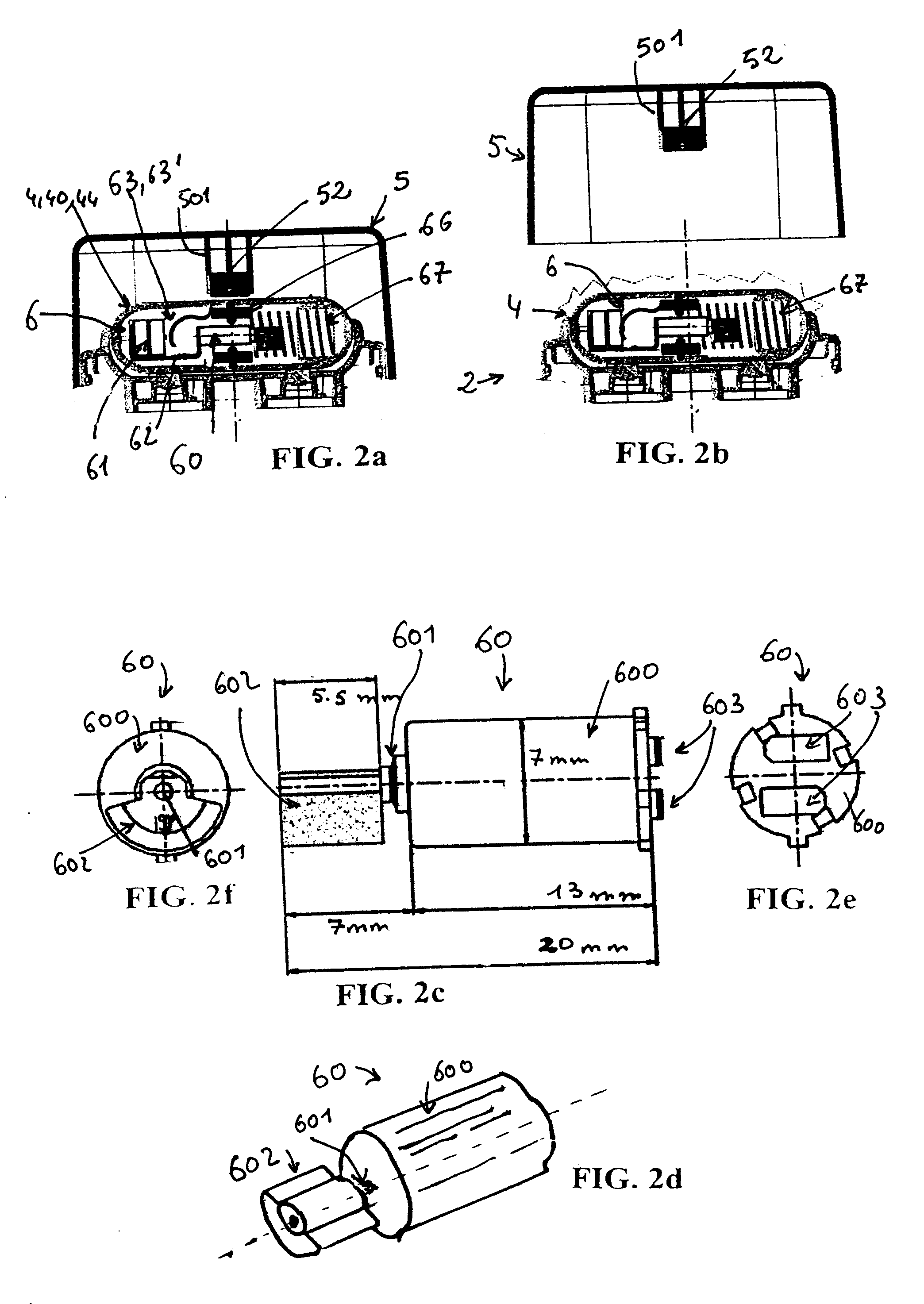
[0107] a cap 5 according to the drawings of FIGS. 6a to 6g, the cap also including at least one axial projection 501, as shown in FIGS. 2a and 2b, so as to then attach an upper magnet 52;

[0108] two hollow half-shells 440, 440′, according to the drawings of FIGS. 7a to 7d, so as to be capable of then forming said hollow roller 44, 44′″;

[0109] a support 45, intended to receive said hollow roller 44, 44′″, according to the drawings of FIGS. 3a to 3e;

[0110] two valves 7 according to the drawings of FIGS. 4a to 4f.

[0111] The support 44 includes an upper peripheral lip 451 defining an upper cavity 46 capable of housing said hollow roller 44′″ forming said rotatable part 44, a circular lip 450 ensuring sealed cooperation with the u...

example 2a

[0122] This example describes producing a plurality of alternative distributor-applicators 1 with a cylindrical shape and an H / D ratio greater than 4 were also produced, as shown in FIGS. 8a to 8f, with H being equal to 88 mm and D being equal to 19.75 mm.

[0123] To do this, a vibration generating device 6 including a box 68 containing the parts constituting said generator was produced, the electrical contact capable of being established by a manual axial pressure exerted on the upper portion of the box 68, in the alternative of FIG. 8f, or on the lower portion of the box, in the case of the alternatives of FIGS. 8b, 8c, 8d and 8e.

[0124] In all of these alternatives according to FIGS. 8b to 8f, the box 68 is housed in the so-called main cavity 30 of the container 3, the base of the container being closed off by an end cap 32.

example 2b

[0125] The alternative according to FIG. 8b was produced. In this alternative:

[0126] the application means 4 form a distinct part of said body 3 and include a central membrane 42 forming said application surface 41 equipped with an upper opening 40, and a peripheral portion 43 capable of being snapped onto said body 3, 3′;

[0127] the cap 5 includes a first projection 500 intended to close off the upper opening 40 when the distributor-applicator 1 is closed;

[0128] the vibration generating device 6 includes an axial rod 64′ as vibration transmission means 64.

[0129] In this alternative, the filling of the container can be done either by the top or by the bottom.

[0130] When it is done by the top, a first sub-assembly of parts is formed, including the cap 5 and the application means 4 snapped on, the second sub-assembly of parts including the container 3 equipped with the end cap 32 and the vibration generating device 6.

[0131] When it is done by the bottom, a first sub-assembly of p...


PUM


Abstract

A distributor-applicator includes a body having a container for containing a product and application means integrated with the container. The application means can be in communication with the container through an upper opening and includes an application surface for application of the product, and a cap cooperating with the body so as to protect the application means when the distributor-applicator is not being used. The body includes a vibration generator, a power source, an associated electric circuit, and a switch for starting and stopping the generator.

Description

BACKGROUND [0001] Ball distributor-applicators are shown, for example, in U.S. Pat. No. 5,810,495, which describes a distributor, typically for a low-viscosity liquid product, including a head equipped with a ball mounted on a spring, as well as an annular valve. Similarly, GB 2 044 683-A describes a tube of which the head includes an application ball, while FR 2 836 345, in the applicant's name, describes a ball measuring applicator. Distributor-applicators with a stationary application surface, as described, for example, in patent applications US 2003 0057236 and US 2002 0014254 are also known. [0002] On one hand, cosmetic products are constantly being developed so as to obtain advantageous new characteristics, but the packaging means are not always suitable for these new products, in particular when these products have a rheology unsuitable for the conventional packaging means. [0003] Second, new application means for the application of all types of products are constantly being ...

Claims


Application Information

Patent Timeline
IPC IPC(8): B43K7/00
CPCA45D34/041A45D2200/207
Inventor MILESI, FREDERICDIEUDONAT, FABRICE
Owner ALCAN PACKAGING BEAUTY SERVICES
Why Eureka
Try Eureka