Coin lock

a technology of coin lock and coin, applied in the field of coin lock, can solve the problems of not being able to operate the lock, not being able to require the insertion of two coins, and the lock is relatively complicated, and achieves the effect of small thickness, simple and space-saving

Active Publication Date: 2012-01-17
ASSA
View PDF3 Cites 2 Cited by
  • Summary
  • Abstract
  • Description
  • Claims
  • Application Information

AI Technical Summary

Benefits of technology

[0009]Another object is to provide such a coin lock which is simple and space-saving, and which has a relatively slight thickness.
[0010]Yet another object is to provide such a coin lock which is simple and whose use is intuitive, and easy to understand.

Problems solved by technology

Thus, with this lock, it is not possible to require insertion of two coins to enable the use of the lock.
However, this lock does not allow the lock to operate only after different coins, that is to say two coins of different value, have been inserted in the lock.
However, the lock is relatively complicated and requires a relatively large thickness crossways to the direction of movement of the bolt.
This can be a disadvantage for the use of the lock.

Method used


Image

  • Coin lock
  • Coin lock
  • Coin lock

Examples


Embodiment Construction

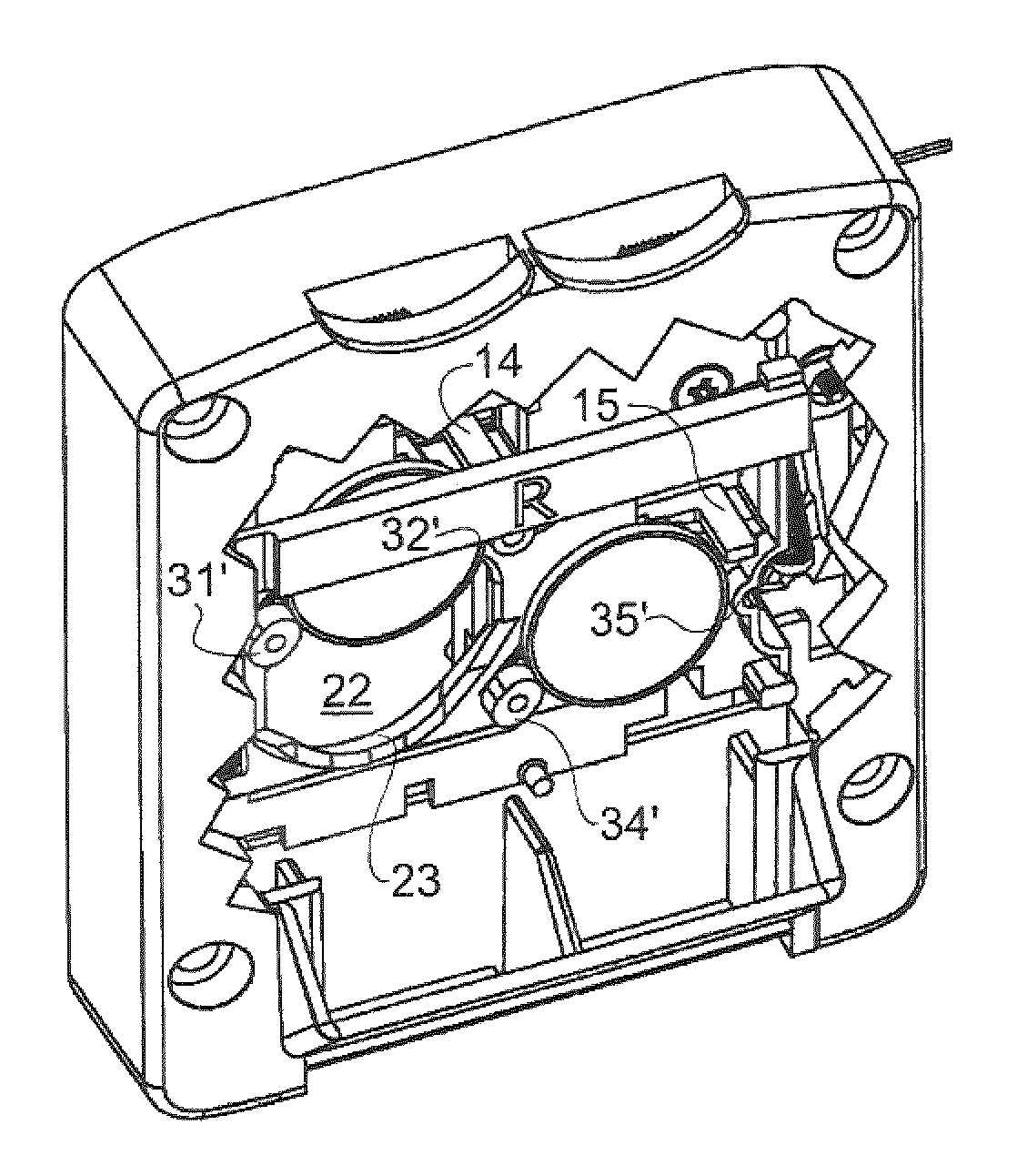
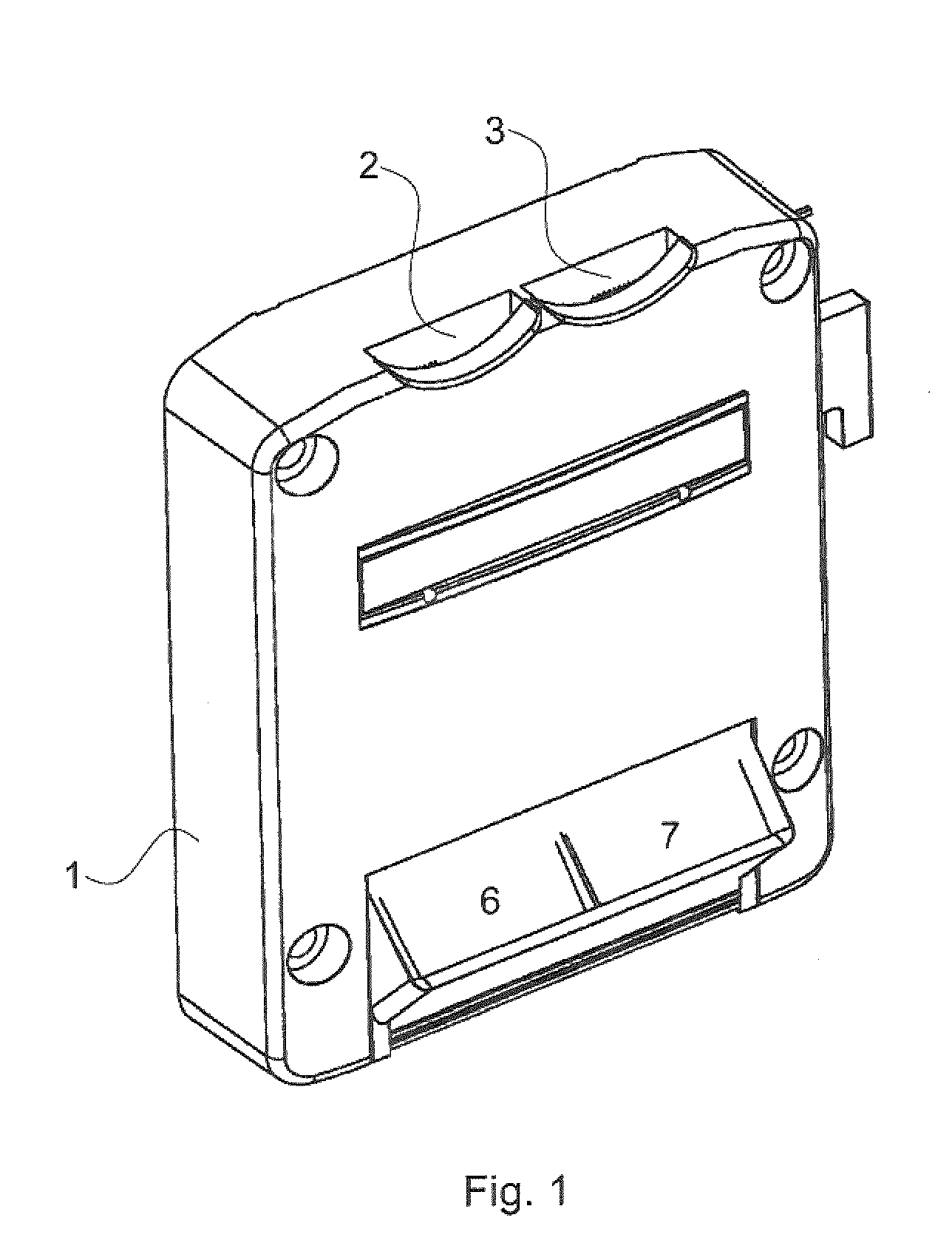
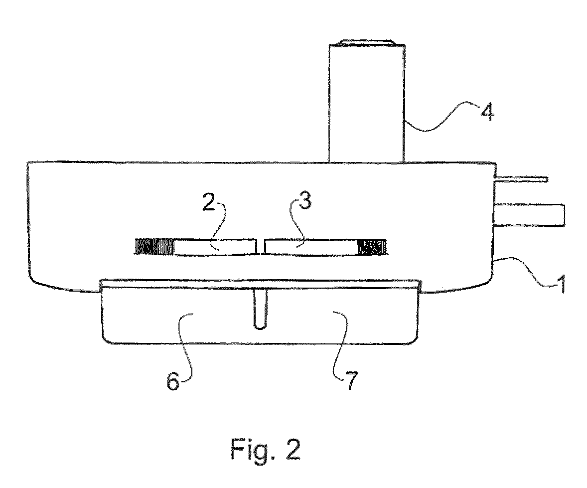
[0029]The coin lock shown in FIG. 1-4 comprises a lock housing 1 or a lock box which has two oblong coin openings 2, 3 arranged in line with each other for insertion of a first (A) and a second (B) coin. The coin lock also comprises a lock cylinder 4, whose core (not shown) engages with a follower 5. A first 6 and a second 7 coin return container are arranged at the lower part of the coin lock and are accessible from the outside of the coin lock. In the lock housing, a bolt piece 8 is able to move between a rear and a forward position. A bolt 9 is firmly connected via a screw 10 to the bolt piece 8 and can move relative to the lock housing together with the bolt piece 8. The follower 5 is connected to the bolt by means of a pin 11. The lock housing 1, the bolt piece 8, the bolt 9 and the follower 5 are configured such that rotation of the follower in a locking direction first produces an essentially horizontal displacement of the bolt 9 and the bolt piece 8 to a forward extended pos...


PUM


Abstract

Coin lock comprising a lock housing (1) with two coin openings (2, 3) for insertion of coins (A, B) which enable operation of the coin lock, a bolt piece (8) which is connected to a bolt (9) and is arranged in the lock housing and able to move between a forward and a rear position, and a first and a second coin sensing device, each of which comprises a first (31, 31′, 34-, 34′) and a second (32, 32′, 35; 35′) carrier device to carry a coin with a predetermined minimum diameter, inserted through one of the coin openings, and a hook (14, 15) which; in absence of a coin with the predetermined minimum diameter, borne by the carrier device, and engaging with the bolt piece, prevents the bolt piece from being moved to the forward position, and which, in the presence of a coin with the predetermined minimum diameter, borne by the carrier device, allows the bolt piece to be moved into the forward position. The carrier devices (31, 31′, 32, 32′, 34, 34′, 35, 35′) of the first and second coin sensing devices are arranged at the same side of the bolt piece (8).

Description

BACKGROUND AND FIELD OF THE INVENTION[0001]The invention relates to a coin lock and more specifically to a coin lock of the kind indicated in the preamble of claim 1.[0002]Such coin locks can be used, for example, in cabinets and storage boxes at public places such as sports halls, public swimming baths, train stations, airports and the like.[0003]The coin locks can operate on the pawn principle, when the coin inserted is returned after use, or on the pay principle, when the coin is not returned.[0004]With such coin locks it can be desirable for the lock to operate only after two coins have been inserted in the lock. In particular, it can be desirable for two coins of different value to be required to operate the lock.PRIOR ART[0005]EP 0 945 836 A describes a coin lock which can be operated after a coin has been inserted in the lock. Thus, with this lock, it is not possible to require insertion of two coins to enable the use of the lock.[0006]DE 31 24 180 A1 describes a coin lock wh...

Claims


Application Information

Patent Timeline
Patent Type & Authority Patents(United States)
IPC IPC(8): G07F5/02
CPCG07F5/06G07F17/12Y10S70/41G07F5/02
Inventor HAGGSTROM, AKEJONSSON, ROLANDH
Owner ASSA
Why Eureka
Try Eureka