Method for manufacturing camera modules and a camera module array

a technology of camera modules and camera modules, applied in the field of manufacturing camera modules and camera module arrays, can solve problems such as sensor damag

Active Publication Date: 2019-03-21
ROBERT BOSCH GMBH
View PDF0 Cites 0 Cited by
  • Summary
  • Abstract
  • Description
  • Claims
  • Application Information

AI Technical Summary

Benefits of technology

[0042]This specific embodiment of the present invention offers the advantage that the method deliver

Problems solved by technology

Since the protective layer may be impervious to light, this wou

Method used


Image

  • Method for manufacturing camera modules and a camera module array
  • Method for manufacturing camera modules and a camera module array
  • Method for manufacturing camera modules and a camera module array

Examples


Embodiment Construction

[0051]FIG. 5 depicts by way of example, a finished camera module array 500. Camera module array 500 has been manufactured on a cohesive conductor foil, which in this exemplary embodiment forms a shared circuit carrier.

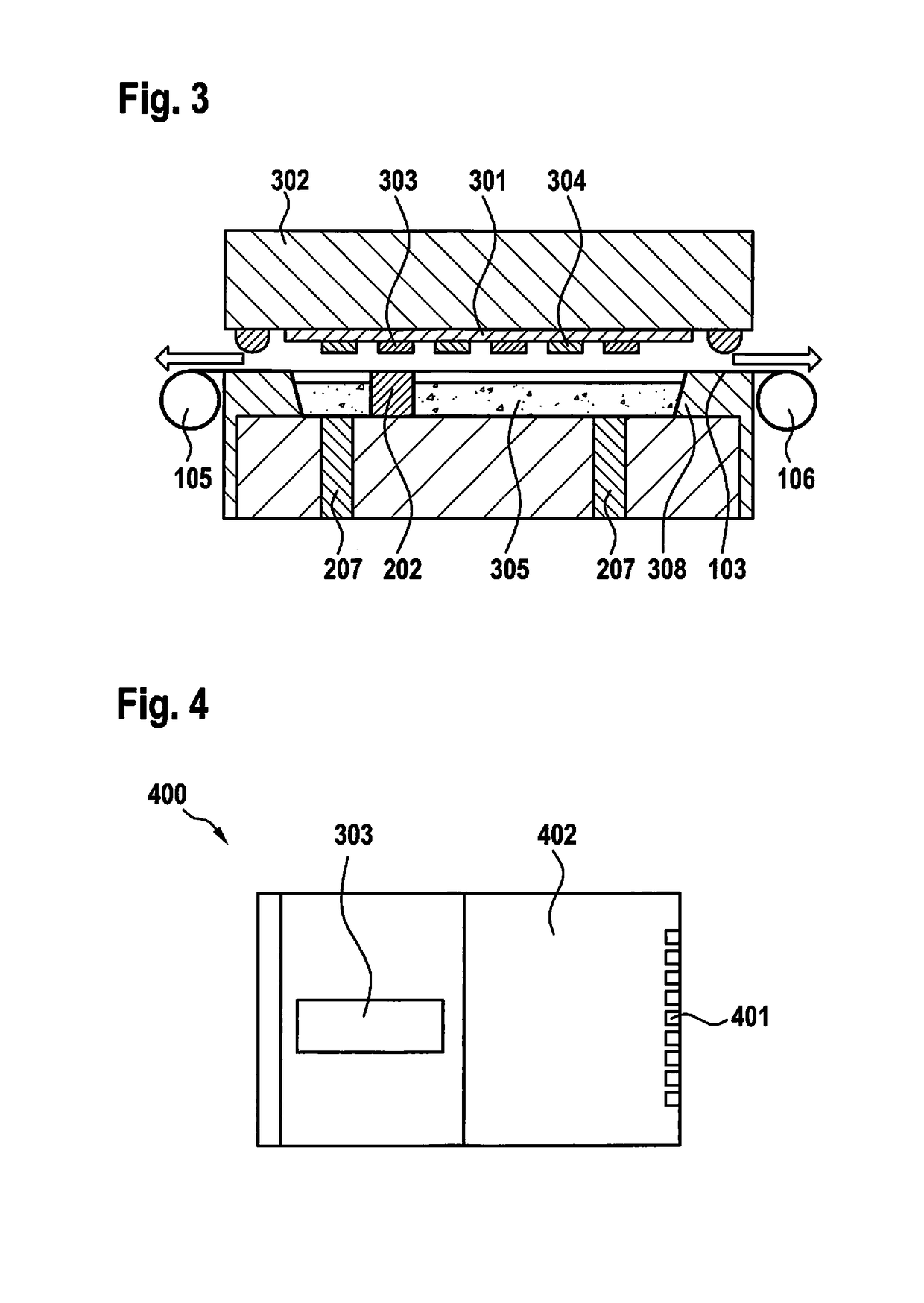
[0052]Camera module array 500 is made up of multiple camera modules 400, which may assume different dimensions and shapes. Depicted by way of example in FIG. 4 is a camera module 400 made up of a circuit carrier, an image sensor 303 and at least one optical element. Camera module 400 is largely covered by molding compound 402. Only the area above image sensor 303 and the area at contact points 401 were left exposed during the molding process. Depending on the exemplary embodiment, it is also possible for only the area above sensor image 303 to be left exposed, for example, if contact points 401 are located laterally and / or on the rear side of the circuit carrier (i.e., not on the side on which the image sensor is mounted). The optical element is not visible due to its ...


PUM


Abstract

A method for manufacturing a camera module array, made up of at least two camera modules, each camera module including a circuit carrier, an image sensor and at least one optical element, including: mounting the image sensor on the circuit carriers;
applying a protective layer to the circuit carriers, the image sensors not being covered by the protective layer or being left exposed; and mounting the optical elements on the image sensors with the aid of an injection molding process and/or embossing process.

Description

RELATED APPLICATION INFORMATION[0001]The present application claims priority to and the benefit of German patent application no. 10 2017 216 708.4, which was filed in Germany on Sep. 21, 2017, and German patent application no. 10 2018 210 909.5, which was filed in Germany on Jul. 3, 2018, the disclosure which are incorporated herein by reference.FIELD OF THE INVENTION[0002]The present invention relates to a method for manufacturing camera modules and a camera module array.BACKGROUND INFORMATION[0003]Multiple methods are already believed to be understood from the related art for manufacturing camera modules, for example, from DE 10 2006 006 113 A1.SUMMARY OF THE INVENTION[0004]The present invention describes a method for manufacturing a camera module, made up of at least two camera modules, each camera module including a circuit carrier, an image sensor and at least one optical element, including the steps:[0005]mounting the image sensors on the circuit carriers[0006]applying a prote...

Claims


Application Information

Patent Timeline
IPC IPC(8): H04N5/225H01L27/146
CPCH04N5/2257H01L27/14683H04N5/2254H04N5/2258H04N5/2253H04N23/50H01L27/14618H04N23/45H04N23/55H04N23/54H04N23/57
Inventor MATUSEK, ADRIAN SEVERINKUGLER, ANDREASAPELT, STEFANSCHAAF, ULRICH
Owner ROBERT BOSCH GMBH
Why Eureka
Try Eureka