Powder-blasting device

a technology of powder-blasting device and nozzle, which is applied in the field of powder-blasting device, can solve the problems of failure of pinch valve, inability to stop treatment immediately, and take a few seconds, and achieve the effect of being reliable and long-lasting

Active Publication Date: 2021-09-07
FERTON HLDG
View PDF11 Cites 0 Cited by
  • Summary
  • Abstract
  • Description
  • Claims
  • Application Information

AI Technical Summary

Benefits of technology

[0008]Provided herein is a powder-blasting device and components thereof which make the powder-blasting device especially reliable and long-lasting while it is as comfortable to handle as possible.
[0011]It can be regarded as a first basic idea of the invention that the joining unit is detachably (disconnectably, removably) connected or connectable with the stationary unit. This accomplishes that in case of a defective pinch valve, especially a defective lockable tube section, the stationary unit requires no complicated repair, but only the joining unit can be exchanged. It is therefore much faster and less expensive to rectify the defect. Furthermore, the arrangement of the lockable tube section outside the stationary unit prevents that powder enters the interior of the stationary unit in which electronic components, especially control elements, are usually housed. Finally, a user can more easily detect the defect, since the user can see powder being discharged from the joining unit when the pinch valve (the lockable tube section) becomes leaky.
[0013]For a more cost-effective exchange of the joining unit, the latter is not only detachably (disconnectably, removably) connected with the stationary unit, but also with the handpiece. Thus the joining unit including the lockable tube section of the pinch valve can be exchanged separately while the stationary unit as well as the handpiece can be retained.
[0024]According to an alternative embodiment of the invention, the control element is seated in the stationary unit and engages in or acts upon the joining unit to block the tube section. Thus, the control of the control element (such as pneumatic, electrical or electromagnetic) takes place in the stationary unit while the critical tube section is in or on the removable joining unit. This provides the two significant advantages that the joining unit can be manufactured more cost-efficiently since it contains fewer parts, and that there is no need for another connection for regulating the control element (such as a pneumatic control line).
[0026]Preferably, there is an unlocking arrangement for the targeted unlocking of the connection between the joining unit and the stationary unit. Preferably, in a coupled state, the joining unit and the stationary unit are coupled / connected with each other such that the coupling / connection can (only) be unlocked by activating the unlocking arrangement. This ensures that the joining unit and the stationary unit cannot be separated from each other without activating the unlocking arrangement. This provides a secure connection.

Problems solved by technology

However, it is a disadvantage of pinch valves that due to the abrasive effect of the dental powder and the repeated mechanical squeezing of the hose, there is wear and tear which can lead to the failure of the pinch valve.
Yet this leads to the disadvantage that the treatment is not stopped immediately since the pressure in the powder chamber first has to be reduced, which can take a few seconds.

Method used


Image

  • Powder-blasting device
  • Powder-blasting device
  • Powder-blasting device

Examples


Embodiment Construction

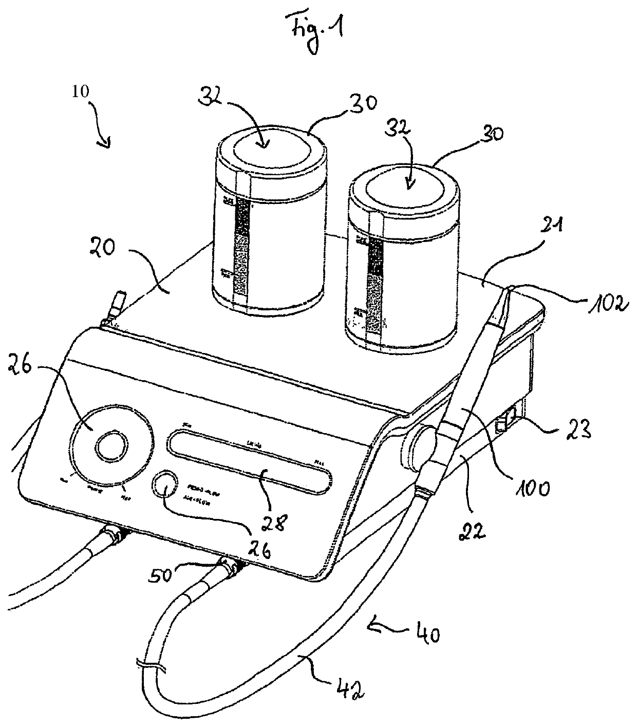
[0041]FIG. 1 shows the basic design of a powder-blasting device 10 according to the invention. The powder-blasting device 10 comprises a stationary unit 20 which can also be called the base station. The stationary unit 20 comprises a housing 21 with a pedestal section 22 for setting the base on a surface such as a table. The housing 21 accommodates control elements for regulating the operation of the powder-blasting device 10, in particular the electronic components. The stationary unit 20 comprises means for supplying compressed gas, in particular compressed air, to a mixing chamber 32 in which a powder-gas mixture, i.e. a powder-air mixture, is produced by means of the compressed gas or compressed air. Furthermore, the stationary unit 20 can comprise an on / off switch 23 as shown in FIG. 1. Finally, the stationary unit 20 may have a control panel or an input arrangement 26 for entering commands and / or a display arrangement 28 for displaying status information. The stationary unit 2...


PUM


Abstract

A powder-blasting device for cleaning the surfaces of teeth via application with a powder-gas mixture, including a stationary unit having a connection region for a mixing chamber for producing the powder-gas mixture, a hand part having a nozzle device for blasting the powder-gas mixture onto a surface of a tooth, and a joining unit for joining the hand part to the stationary unit wherein the joining unit has at least one joining guide between the stationary unit and the hand part, and wherein a tube section that can be blocked via elastic deformation is arranged in a powder-gas line between the mixing chamber and the nozzle device, wherein the joining unit is detachably joined to the stationary unit and the lockable tube section is arranged in the detachable joining unit.

Description

TECHNICAL FIELD[0001]The invention relates to a powder-blasting device for cleaning the surfaces of teeth via application with a powder-gas mixture and to a joining unit for a powder-blasting device.BACKGROUND[0002]Powder-blasting devices (dental abrasive blasting devices) for cleaning, in particular for powder-blasting or polishing, the surfaces of teeth by means of an abrasive tooth cleaning powder (dental powder) are state of the art. Hereby, the dental powder is used to clean the surfaces of teeth via a gaseous carrier medium, usually air, by blasting it onto the surface of teeth. In addition, usually a liquid medium, usually water, is conducted into the patient's mouth via a separate line. The purpose of the liquid is to prevent the powder from spreading in uncontrolled fashion during the dental treatment and to flush away the removed impurity particles including the powder particles that remain in the patient's mouth.[0003]For example, a powder-blasting device of the kind ment...

Claims


Application Information

Patent Timeline
Patent Type & Authority Patents(United States)
IPC IPC(8): A61C3/025
CPCA61C3/025
Inventor LEBRETON, ETIENNELIMON, MARTINBEANI, FLORENT JEAN-CLAUDE GEORGESFRIDEZ, PIERREDONNET, MARCEL
Owner FERTON HLDG
Why Eureka
Try Eureka