Connection of a prosthesis structure with an implant structure

a technology of prosthesis structure and implant structure, which is applied in the field of connection devices, can solve the problems of high consumption of retention parts, difficulty and labor, and irregularly not being able to place implant structures exactly at the desired targ

Active Publication Date: 2013-04-25
INSTITUT STRAUMANN AG
View PDF7 Cites 12 Cited by
  • Summary
  • Abstract
  • Description
  • Claims
  • Application Information

AI Technical Summary

Benefits of technology

[0011]In that the adjacent outer surface of the retention rim and inner surface of the holding rim are at least partly not contacting each other but are spaced from each other when essentially no radial forces are acting on the holding rim of the holding shell and on the retention rim of the retention insert, it can, i.a., be achieved that the retention insert is connected relatively loosely with the holding shell when the connection device has not yet been placed on the implant structure. Advantageously, this loose connection is just sufficient for holding the retention insert in the holding shell to thus allow a comfortable handling. This loose connection can allow the retention insert to be relatively easily removed from and inserted in the holding shell without having to be substantially deformed or strained in any other way. Thus, it is possible to insert and remove the retention insert gently, which can improve the flexibility and lifetime of the connection device.
[0031]Preferably, the mounting tool comprises a mounting head which has an insertion portion being arrangeable in a retainer formed by said retention rim of said retention insert and an end side of said retention insert, such that said retention insert is held at said mounting head. Such a mounting tool allows for a particularly suitable mounting and at the mean time a particularly suitable demounting. In particular, the insertion portion can be shaped in correspondence with the retainer of the retention insert such that the retention insert can be held in an essentially form-fit manner by the mounting tool. Therefore, a radial outer surface of said insertion portion of said mounting head preferably is convexly curved. Preferably, the mounting tool has an elongated basic form wherein said mounting head is arranged at one of its longitudinal ends and said demounting head at the other of its longitudinal ends. Such an arrangement of the mounting tool allows for providing the mounting tool in an appropriate compact shape.

Problems solved by technology

A problem nowadays often occurring in artificial dentures is the fact that the position of the dental implant or the implant structure depends on various factors, for example the condition of the jaw bone, the progress of a possible osseointegration and in particular also an exact insertion.
Accordingly, nowadays it is regularly not possible to place implant structures exactly at a desired target place and in a desired target position and connect them with the prosthesis structure.
For such a selection and adaptation of the retention parts during fitting of the prosthesis structure, however, it is often necessary to test different hardnesses of retention parts, which can be difficult and laborious.
Moreover, when being mounted in and dismounted from the corresponding caps, the retention parts are also squeezed and damaged due to the mentioned deformation, which can lead to a high consumption of retention parts.
Moreover, during everyday use of the prosthesis structure and as a consequence of the mentioned compensation function, the retention bodies are strained so much by deformation as well as a non-uniform mounting and dismounting of the prosthesis structure that they have to be renewed regularly, which can be laborious and expensive.
Finally, dirt particles can collect in the hollow spaces formed by the deformation of the retention parts, which is mostly not desired.

Method used


Image

  • Connection of a prosthesis structure with an implant structure
  • Connection of a prosthesis structure with an implant structure
  • Connection of a prosthesis structure with an implant structure

Examples


first embodiment

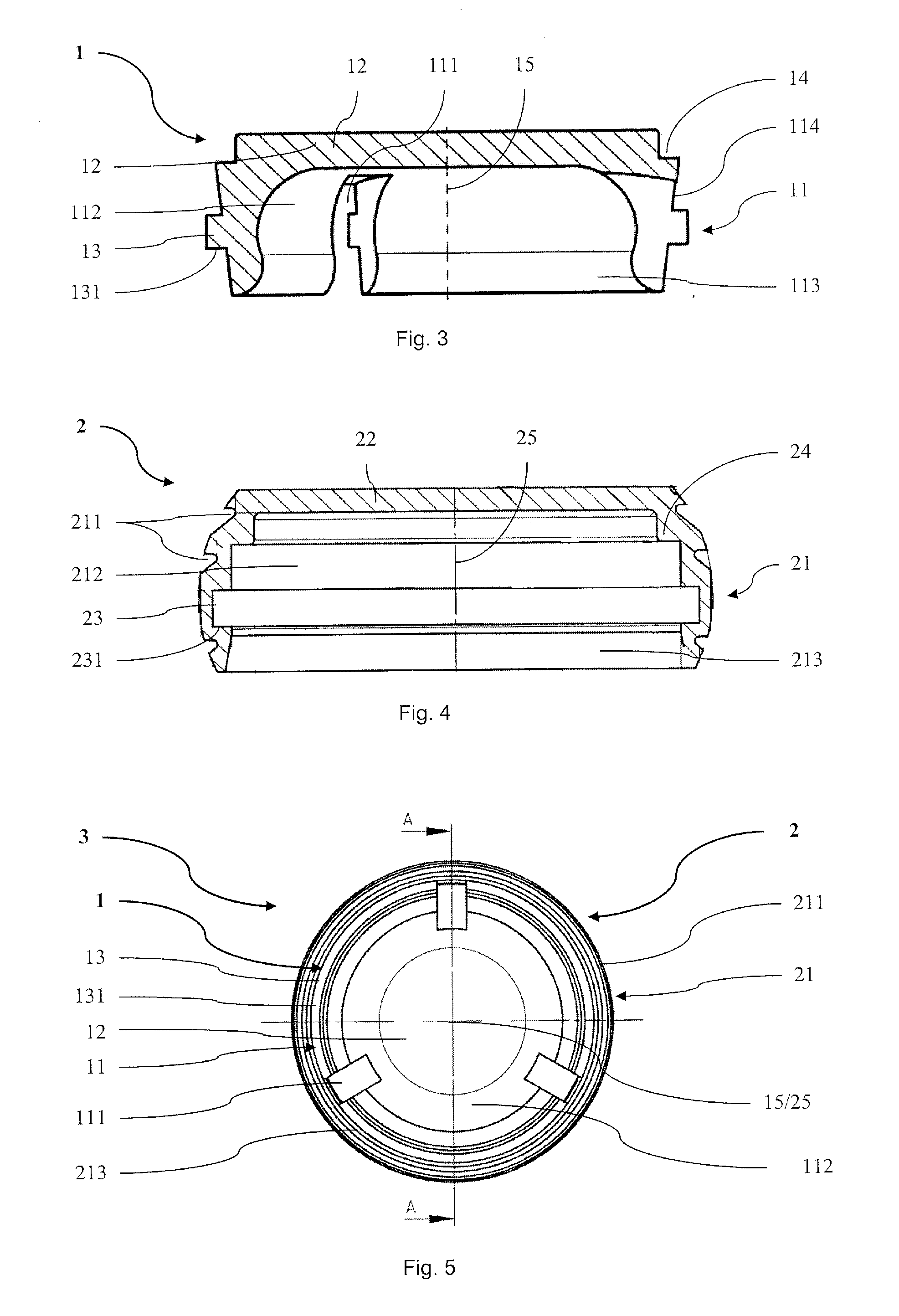
[0037]FIG. 5 shows a bottom view of a connection device, wherein the retention insert of FIG. 1 is arranged as intended in the holding shell of FIG. 4;

[0038]FIG. 6 shows a cross-sectional view along the line A-A of the connection device of FIG. 5;

[0039]FIG. 7 shows a cross-sectional view of the detail B of the connection device of FIG. 6;

[0040]FIG. 8 shows a perspective view of a second embodiment of a retention insert according to the invention of a second embodiment of a connection device according to the invention;

[0041]FIG. 9 shows a perspective view of a third embodiment of a retention insert according to the invention of a third embodiment of a connection device according to the invention;

[0042]FIG. 10 shows a partial sectional side view of a first embodiment of a mounting tool according to the invention;

[0043]FIG. 11 shows a bottom view of a second embodiment of a connection device according to the invention with a second embodiment of a holding shell and a fourth embodiment ...

second embodiment

[0045]FIG. 13 shows a partial sectional side view of a mounting tool according to the invention;

[0046]FIG. 14 shows a side view of a section of the mounting tool of FIG. 13 during mounting of the retention insert of the connection device of FIG. 11 before accommodating it;

[0047]FIG. 15 shows a side view of the section of the mounting tool of FIG. 13 during mounting of the retention insert of the connection device of FIG. 11 after accommodating it;

[0048]FIG. 16 shows a side view of the section of the mounting tool of FIG. 13 during mounting of the retention insert of the connection device of FIG. 11 before inserting it in the holding shell of the connection device of FIG. 11;

[0049]FIG. 17 shows a side view of the section of the mounting tool of FIG. 13 during mounting of the retention insert of the connection device of FIG. 11 after inserting it in the holding shell of the connection device of FIG. 11;

[0050]FIG. 18 shows a side view of the section of the mounting tool of FIG. 13 afte...

third embodiment

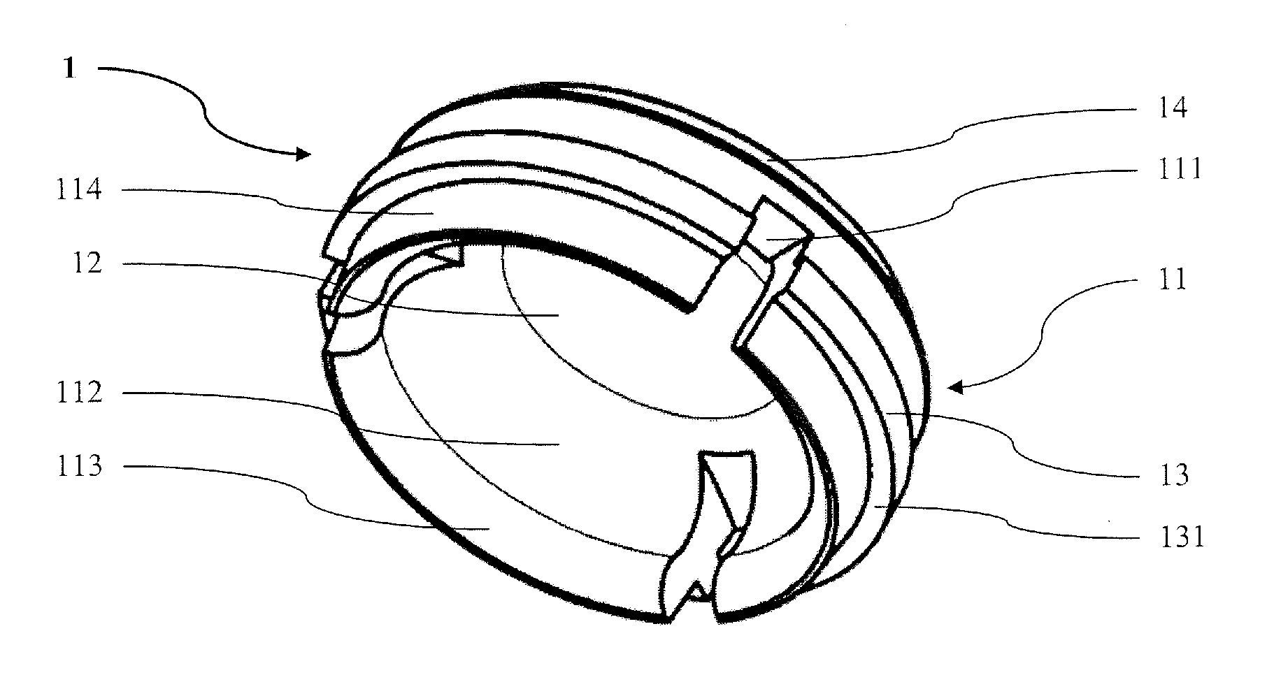
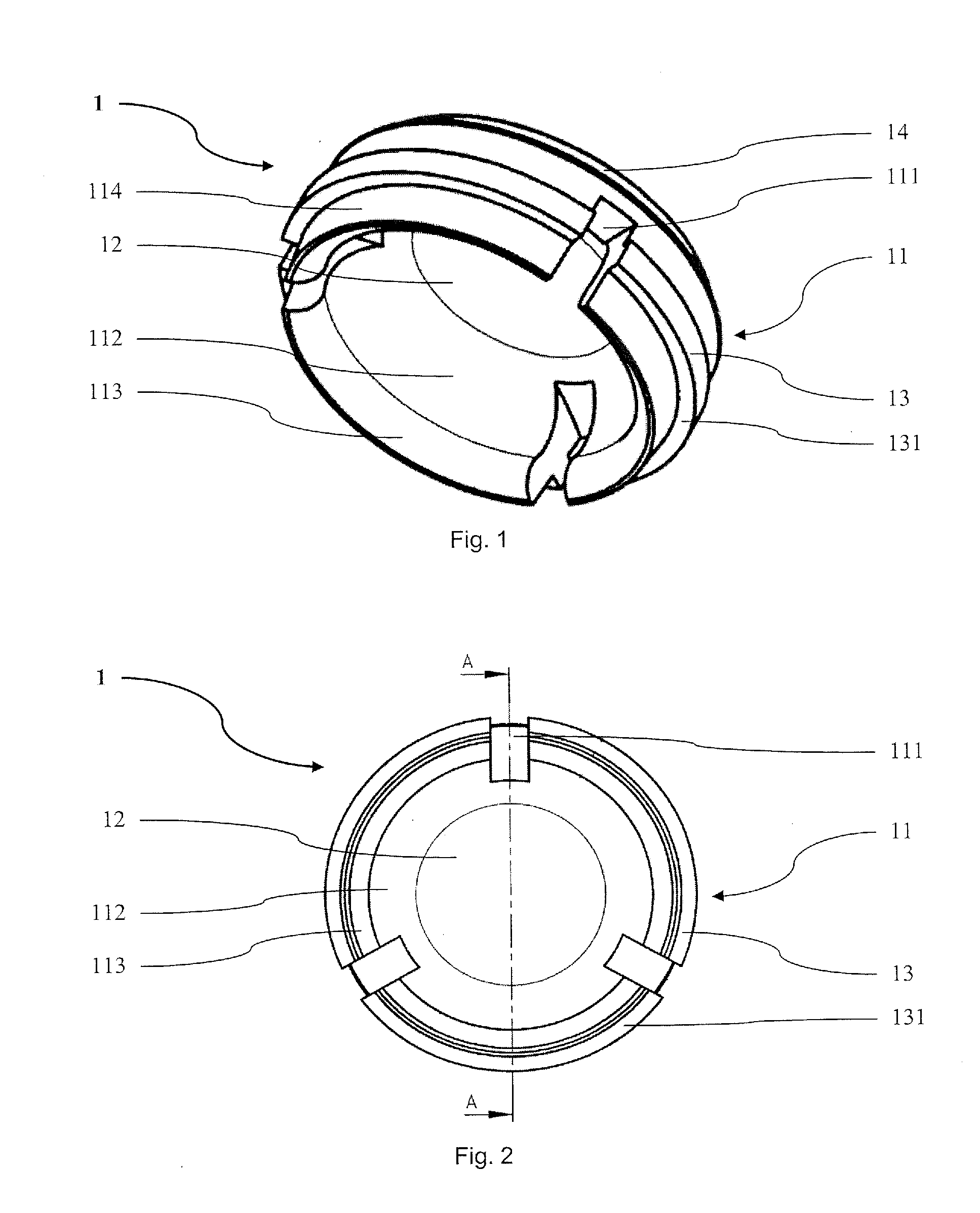
[0068]FIG. 9 shows a retention insert 18 according to the invention, which retention insert is designed substantially analogously to the retention inserts 1 and 19 described above, except for the fact that it comprises a retention rim 118 having six recesses 1118. In particular, the retention insert 18 comprises an end side 128 as well as the retention rim 118 with an outer surface 1148, the six recesses 1118 spaced uniformly with respect to each other in the circumferential direction, as well as lamella portions 1128 arranged therebetween. The recesses 1118 are angled about 60° relative to each other. They start from an end of the retention rim 118 facing away from the end side 128 and extend in the direction of the end side 128 over more than 80% of the retention rim 118. The inner surfaces of the lamella portions 1128 have a curved portion 1138. The retention insert 18 further comprises a step 148 and a projection 138 having a projection supporting surface 1318. The retention ins...


PUM


Abstract

A connection device for connecting a prosthesis structure with an implant structure comprises a holding shell and a retention insert. The retention insert comprises an end side and a substantially ring-shaped retention rim projecting therefrom. The holding shell comprises an end side and a substantially ring-shaped holding rim projecting therefrom. The holding rim and the end side of the holding shell form a retainer in which the retention insert can be arranged such that an outer surface of the retention rim is adjacent to an inner surface of the holding rim. Moreover, the outer surface of the retention rim is at least partly spaced from and adjacent to the inner surface of the holding rim when the retention insert is arranged in the retainer of the holding shell and when essentially no radial forces are acting on the holding rim and on the retention rim. In that the adjacent outer surface of the retention rim and inner surface of the holding rim are at least partly not contacting each other but are spaced from each other when essentially no radial forces are acting on the holding rim and on the retention rim, it can, i.a., be achieved that the retention insert is connected relatively loosely with the holding shell when the connection device has not yet been placed on the implant structure. This loose connection can allow the retention insert to be relatively easily removed from the holding shell and inserted in the holding shell without having to be substantially deformed or strained in any other way. Thus, it is possible to insert and remove the retention insert gently, which can improve the flexibility and lifetime of the connection device.

Description

TECHNICAL FIELD[0001]The invention relates to a connection device as well to a corresponding retention insert, a corresponding method and a corresponding mounting tool. Connection devices of this kind, which comprise a holding shell and a retention insert, wherein the holding shell has an end side and a substantially ring-shaped holding rim projecting therefrom and the retention insert has an end side and a substantially ring-shaped retention rim projecting therefrom, and wherein the holding rim and the end side of the holding shell form a retainer in which the retention insert can be arranged such that an outer surface of the retention rim of the retention insert is located adjacent to an inner surface of the holding rim of the holding shell, can be used for connecting a dental prosthesis structure with a dental implant structure or with a capped tooth.PRIOR ART[0002]In dentistry, damaged or diseased teeth are nowadays regularly replaced with artificial dentures. Such dentures can ...

Claims


Application Information

Patent Timeline
Patent Type & Authority Applications(United States)
IPC IPC(8): A61C8/00A61C5/08A61C5/35A61C5/70
CPCA61C8/0048A61C8/0089A61C13/2656A61C8/0062B25B27/00A61C8/0016A61C8/005A61C13/12A61C5/08A61C8/00A61C8/0057A61C8/0093A61C13/267A61C5/70A61C5/35
Inventor FISCHLER, TITUSFISCHLER, ELIZABETHBÄCHLER, MARTINBÄCHLER, JÜRGSCHAFFNER, ROLAND
Owner INSTITUT STRAUMANN AG
Why Eureka
Try Eureka