Hand-held power tool with spring-loaded handle suspension

Active Publication Date: 2007-06-28
HILTI AG
View PDF7 Cites 11 Cited by
  • Summary
  • Abstract
  • Description
  • Claims
  • Application Information

AI Technical Summary

Benefits of technology

[0008]An object of the present invention is to avoid the disadvantages discussed above in a portable hand-held power tool wit

Problems solved by technology

Consequently, at extreme load conditions of the hand-held power tool, at which a pivot range of the handle suspensions provided for isolating the vibration can be exceeded, the pivot range is limited by a damping end stop.
Advantageously, both a pivot motion of the first handle suspension and a

Method used


Image

  • Hand-held power tool with spring-loaded handle suspension
  • Hand-held power tool with spring-loaded handle suspension
  • Hand-held power tool with spring-loaded handle suspension

Examples


Embodiment Construction

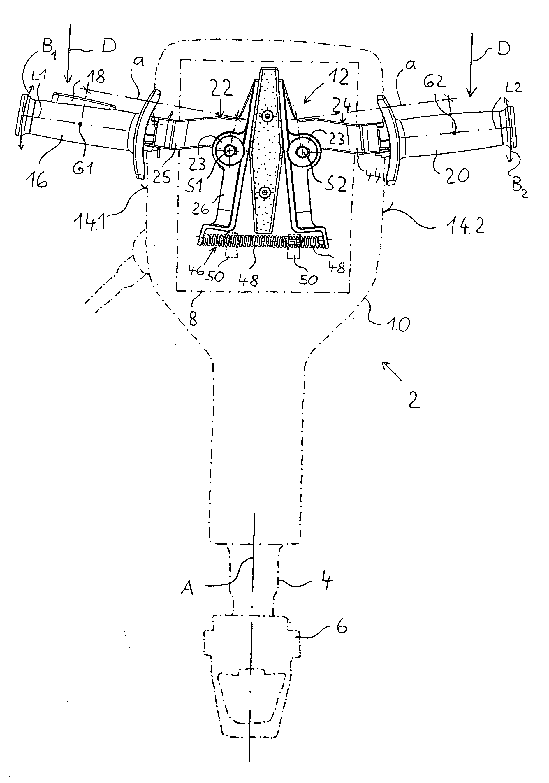
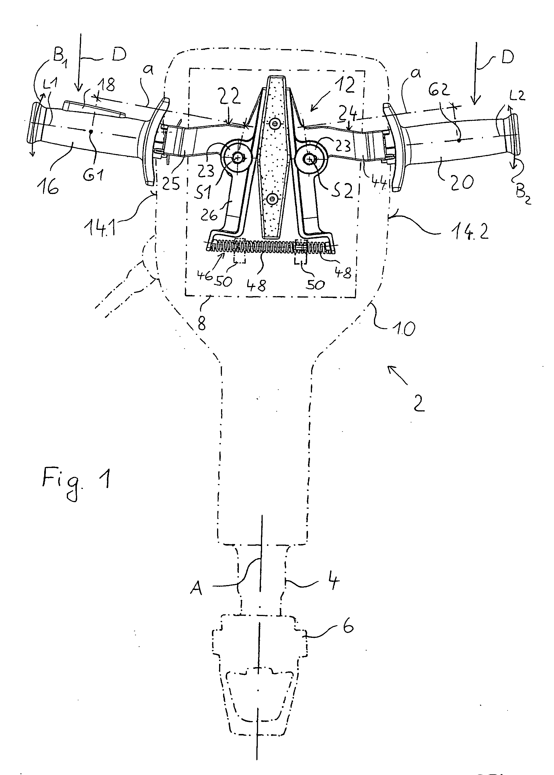
[0022]FIG. 1 shows a portable hand-held power tool 2 in the form of an electropneumatically operated chisel hammer, which carries a tool holder 6 on a tool spindle 4 to which blows are imparted by a drive assembly 8, not shown in detail, along an operational axis A.

[0023]As an alternative to the design of the chisel hammer, the hand-held power tool 2 can also be formed as a drilling hammer or a combination chisel and drill hammer, in which the tool holder 6 in addition to being imparted with percussion motion, is also imparted with a rotating motion around the operational axis A. In this case, the drive assembly 8 comprises an additional transmission (not shown in detail).

[0024]The hand-held power tool 2 comprises a tool housing 10 in which the drive assembly 8 is located. Furthermore, a handle assembly 12 is provided, which comprises a first handle 16 projecting from a first side 14.1 of the housing 10, which is provided with a first effective point of application G1 which is forme...


PUM


Abstract

A portable hand-held power tool (2), especially in the form of a drilling or chisel hammer, includes a drive assembly (8) located in the tool housing (10) for driving a tool spindle (4) along an operational axis (A), a first handle (16) which is rotatable around a first pivotal axis (S1) by a first handle suspension (22), a second handle (20) located on the opposite sides (14.1, 14.2) of the housing which is rotatable around a second pivotal axis (S2) by a second handle suspension (24), and spring elements for retaining the handles (16, 20) in their initial position, with the first and second handle suspensions (22, 24) extending partially circumferentially about the drive assembly (8).

Description

BACKGROUND OF THE INVENTION[0001]1. Field of the Invention[0002]The present invention relates to a portable hand-held power tool, especially in the form of a drilling or chisel hammer and including a drive assembly for driving a tool spindle along an operational axis, which comprises a drive assembly in the form of an electric motor and a movement converter in the form of a percussion mechanism, if necessary in combination with a transmission. The drive assembly is located in the tool housing. Further, the hand-held power tool includes a first handle pivotable by a first handle suspension around a first pivotal axis, and a second handle pivotable around a second pivotal axis by a second handle suspension. Both handles extend from the opposite sides of the housing and are respectively held in their initial position by spring means.[0003]2. Description of the Prior Art[0004]Hand-held power tools of the type discussed above generate strong vibrations during operation along the operatio...

Claims


Application Information

Patent Timeline
IPC IPC(8): B25D17/24
CPCB25D17/043B25G1/01
Inventor BUCHENAU, ALEXANDERPLANK, UTOHAMMERSTINGL, STEFAN
Owner HILTI AG
Why Eureka
Try Eureka