Oblique projection optical system and projection type display apparatus using the same

Active Publication Date: 2010-07-08
MAXELL HLDG LTD
View PDF6 Cites 36 Cited by
  • Summary
  • Abstract
  • Description
  • Claims
  • Application Information

AI Technical Summary

Benefits of technology

[0024]wherein the particular lens has such a shape that a portion of the aspheric shape symmetric about the particular optical axis is truncated to remarkably

Problems solved by technology

JP-A-2002-350774, on the other hand, discloses an adjusting method in which a free-form curved mirror is simply moved, and fails to take into consideration a specific method of correcting phenomena unique to the oblique projection opt

Method used


Image

  • Oblique projection optical system and projection type display apparatus using the same
  • Oblique projection optical system and projection type display apparatus using the same
  • Oblique projection optical system and projection type display apparatus using the same

Examples


Embodiment Construction

[0058]The best aspect for implementing the invention is explained in detail below with reference to the accompanying drawings. Incidentally, in each of the drawings, elements having a same function are designated by same reference numerals, respectively, and explanations thereof are omitted.

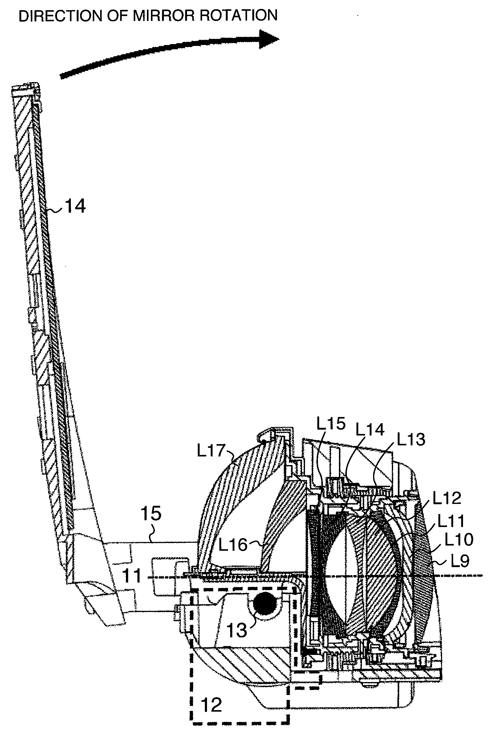
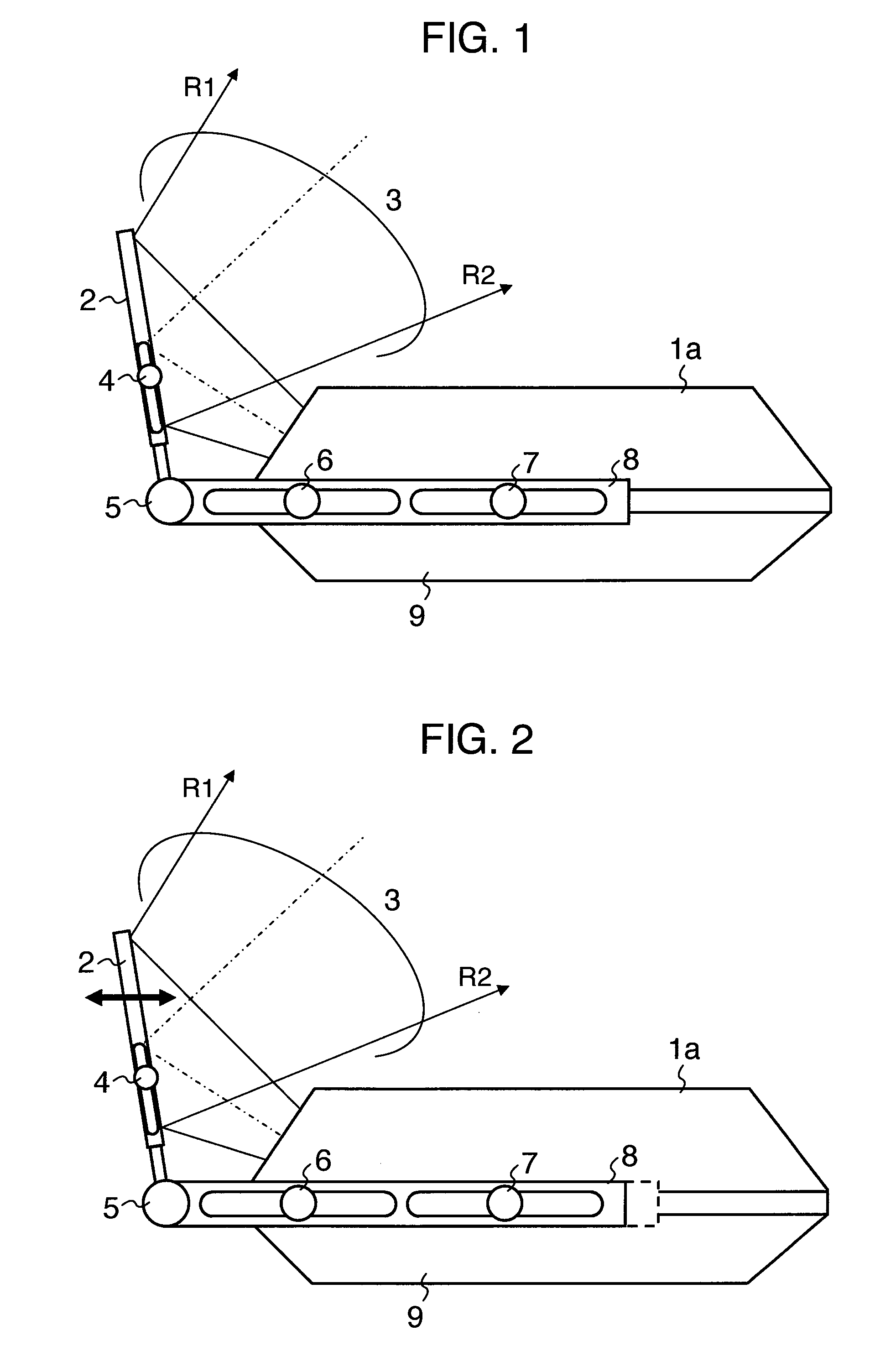
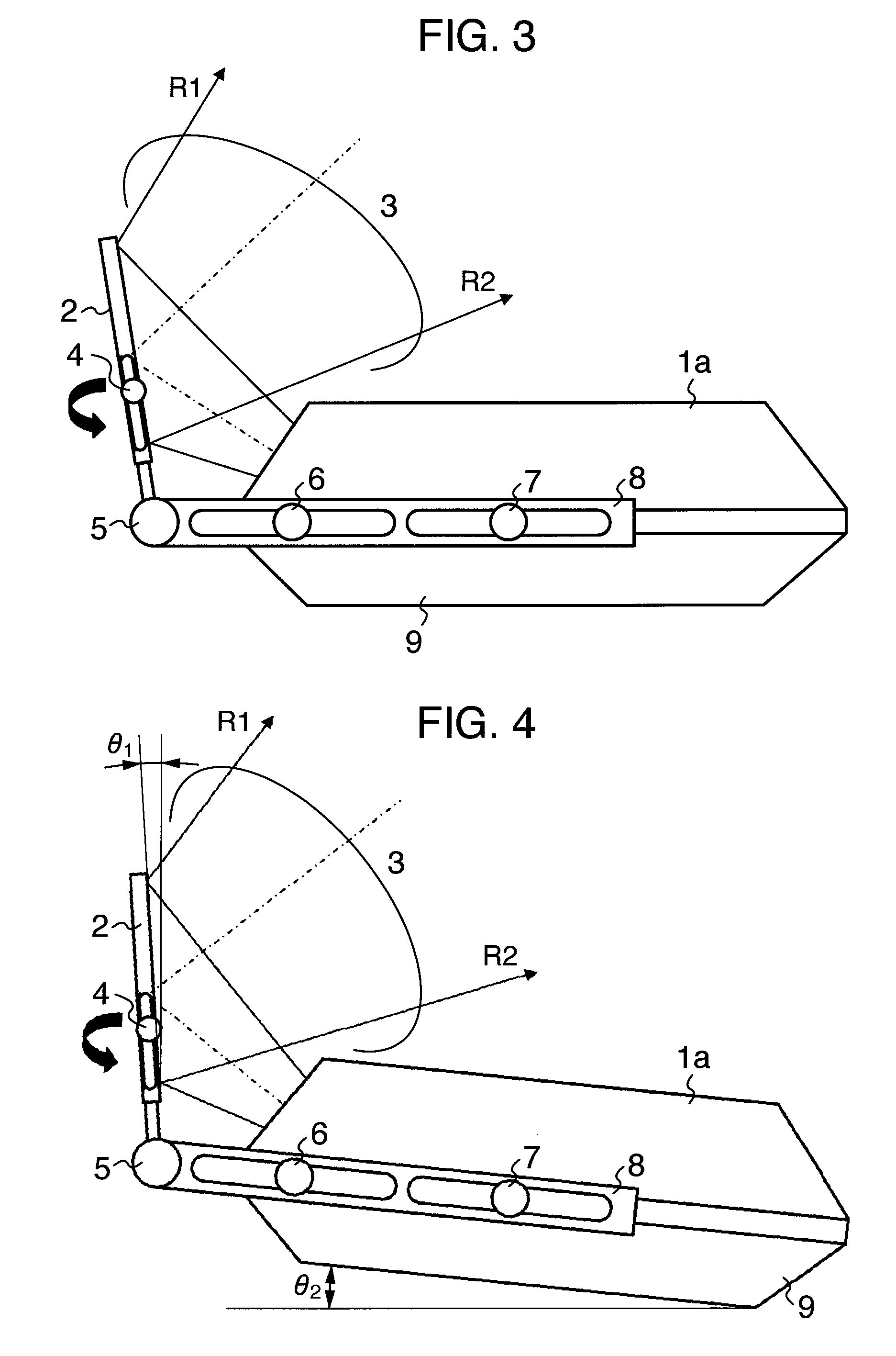
[0059]FIGS. 1 to 3 are side views each schematically illustrating a projection type display apparatus according to an embodiment of the invention. Especially, a projection type display apparatus is provided with an oblique projection optical system (not shown) in which a flat mirror (not shown) is fixed on a fixing frame 2 and an image light flux 3 is returned and projected obliquely on a projection screen directed toward a display screen (not shown). The main parts including the oblique projection optical system described above, an illumination optical system and circuit parts (not shown) are accommodated in a lower housing 9 and an upper housing la.

[0060]In FIGS. 1 to 3, reference numeral 4 des...


PUM

PropertyMeasurementUnit
Lengthaaaaaaaaaa
Lengthaaaaaaaaaa
Lengthaaaaaaaaaa

Abstract

A projection type display apparatus including an oblique projection optical system having a plurality of lenses is disclosed. A lens nearest to a projection screen has a vertical effective image area through which a light flux passes. The lens is arranged at a position not including an optical axis shared by the largest number of lenses among the plurality of lenses. A flat mirror for returning the optical path is arranged between the particular lens and the projection screen at a predetermined angle to the optical axis. An enlarged image obtained by the light flux returned by the flat mirror is formed toward a display screen.

Description

BACKGROUND OF THE INVENTION[0001]This invention relates to a projection type display apparatus for enlarging an image displayed on a display screen of a display device and projecting the enlarged image on a projection screen or a projection board, and a projection optical system thereof, or in particular to a projection type display apparatus for projecting obliquely on the projection screen an image displayed on the display screen of a display device, an optical system thereof, and a method of machining a molded plastic lens constituting the optical system.[0002]In the projection type display apparatus for displaying in an enlarged form, on a projection screen or a projection board, an image on a display screen of a liquid crystal panel of reflection type or transmission type or a displayed image of a display device with an array of a plurality of micro mirrors arranged thereon, it is important not only to produce a sufficiently enlarged image on the projection screen but also to p...

Claims


Application Information

Patent Timeline
IPC IPC(8): G03B21/28G02B13/18G03B21/14B23P15/24
CPCG02B3/02G02B13/16H04N9/3141G02B13/18G03B21/14G03B21/28Y10T29/49995G03B21/006G03B21/30
Inventor HIRATA, KOJIYATSU, MASAHIKOOGURA, NAOYUKI
Owner MAXELL HLDG LTD
Why Eureka
Try Eureka