Swiveling utility machine having swivel deck

a utility machine and swivel technology, which is applied in the direction of soil shifting machines/dredgers, roofs, transportation and packaging, etc., can solve the problems of troublesome assembly, complicated mounting construction, and difficulty in forming the fore-and-aft size of the swivel deck compa

Active Publication Date: 2008-01-22
KUBOTA LTD
View PDF32 Cites 37 Cited by
  • Summary
  • Abstract
  • Description
  • Claims
  • Application Information

AI Technical Summary

Benefits of technology

[0008]A primary object of the present invention is to provide a swiveling utility machine which has a swivel deck formed compact in the fore and aft direction and which yet allows easy mounting of right and left implement controllers, through ingenious layout of the support frame and right and left implement controllers.
[0018]With the above construction, the support frame mounting the right and left implement controllers can be disposed across and over the engine. Therefore, the assembly of e.g. the right and left implement controllers can be very easily carried out, while the swivel deck is formed compact in the fore and aft direction.
[0019]According to one preferred embodiment of the present invention, a fixed cover is attached to a front face of the support frame, a side cover for covering the radiator is attached to the left side of the support frame, and a front face of the side cover, the front face of the fixed cover and the front face of the left implement controller at its retracted posture are arranged side by side substantially in a same plane. With this construction, the front face of the fixed cover, as a raised wall on the rear side of the step, the front face of the side cover and the front face of the left implement controller are arranged substantially flush with little unevenness, so that the step can be formed wider for facilitating the driver's access to the driver's seat.
[0021]Still preferably, a support stay extending over and across the radiator projects from the left side of the support frame, and the lower pivot portion of the left implement controller is supported at a portion of the support stay on the outside of the radiator. With this construction, the radiator and the left implement controller can be supported easily and reliably. Moreover, the left implement controller can be arranged at a position appropriate in the right / left direction and at an appropriate height, without being interfered with by the radiator.
[0022]According to another preferred embodiment of the present invention, on the side of the engine opposite to the access entrance, a hydraulic pump is disposed and a working oil tank and a fuel tank are disposed forwardly of the hydraulic pump and laterally of the driver's seat. With this, the upper structure of the swivel deck may be formed compact in the fore and aft direction, so that the entire swiveling utility machine can be formed even more compact.
[0023]Preferably, a front face and an upper face of the engine are covered by a fixed cover and a rear face of the engine is covered by an openable / closable hood cover, an air-inlet side of the radiator is covered by an openable / closable side cover, and the hydraulic pump, the working oil tank and the fuel tank are covered by a tank cover. This construction facilitates maintenance of the upper structure of the swivel deck.

Problems solved by technology

However, as the right and left implement controllers are supported by separate stays, the mounting construction is complicated and assembly thereof is troublesome.
Although this support frame can support the driver's seat and the right and left implement controllers, as the frame is disposed separately and forwardly of the engine, it is difficult to form the fore-and-aft size of the swivel deck compact.
For this reason, the access step is formed in a rather limited space, making the driver's access to the driver's seat difficult.

Method used


Image

  • Swiveling utility machine having swivel deck
  • Swiveling utility machine having swivel deck
  • Swiveling utility machine having swivel deck

Examples


Embodiment Construction

[0046]Preferred embodiments of the present invention will be described in details with reference to the accompanying drawings.

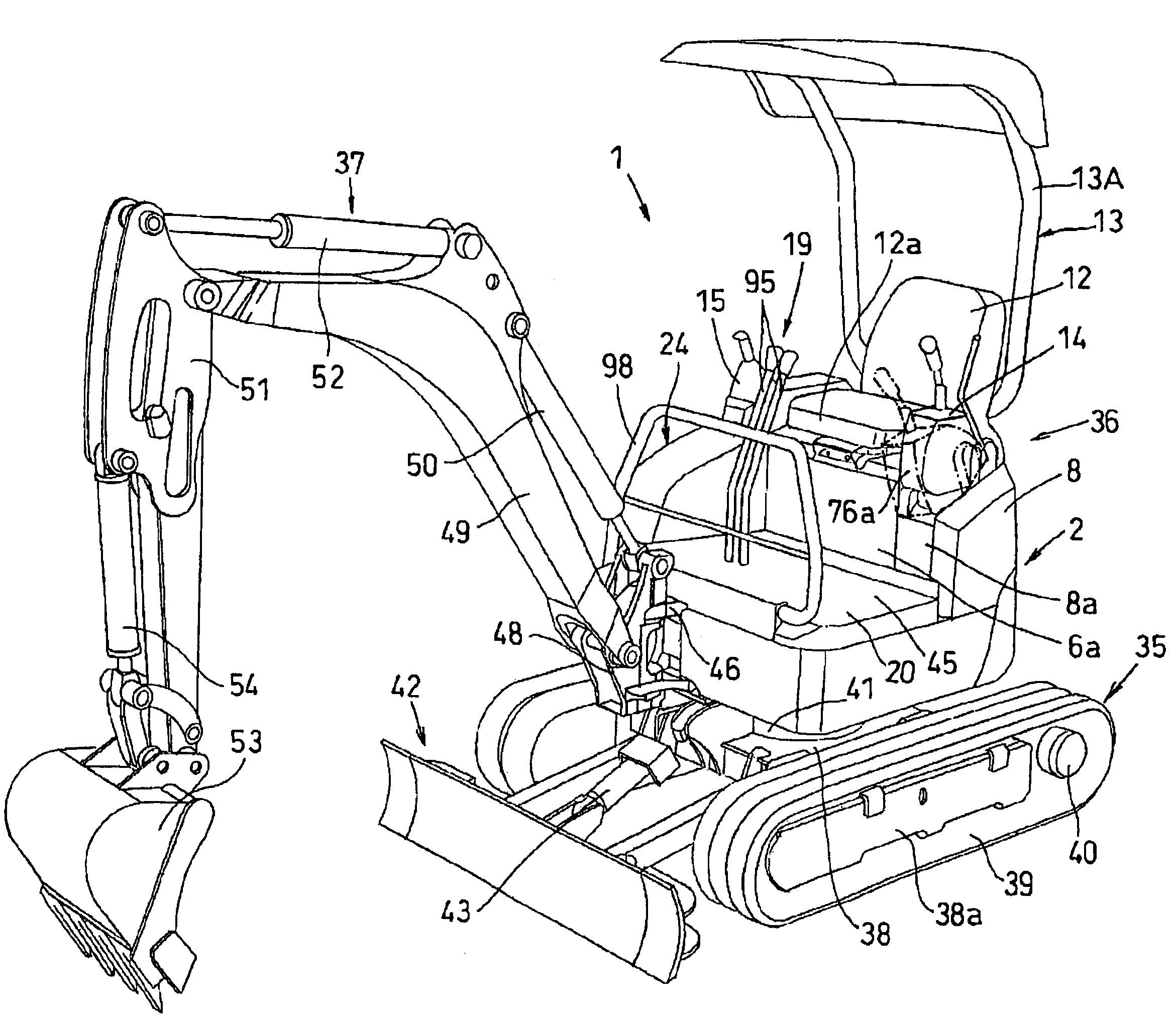
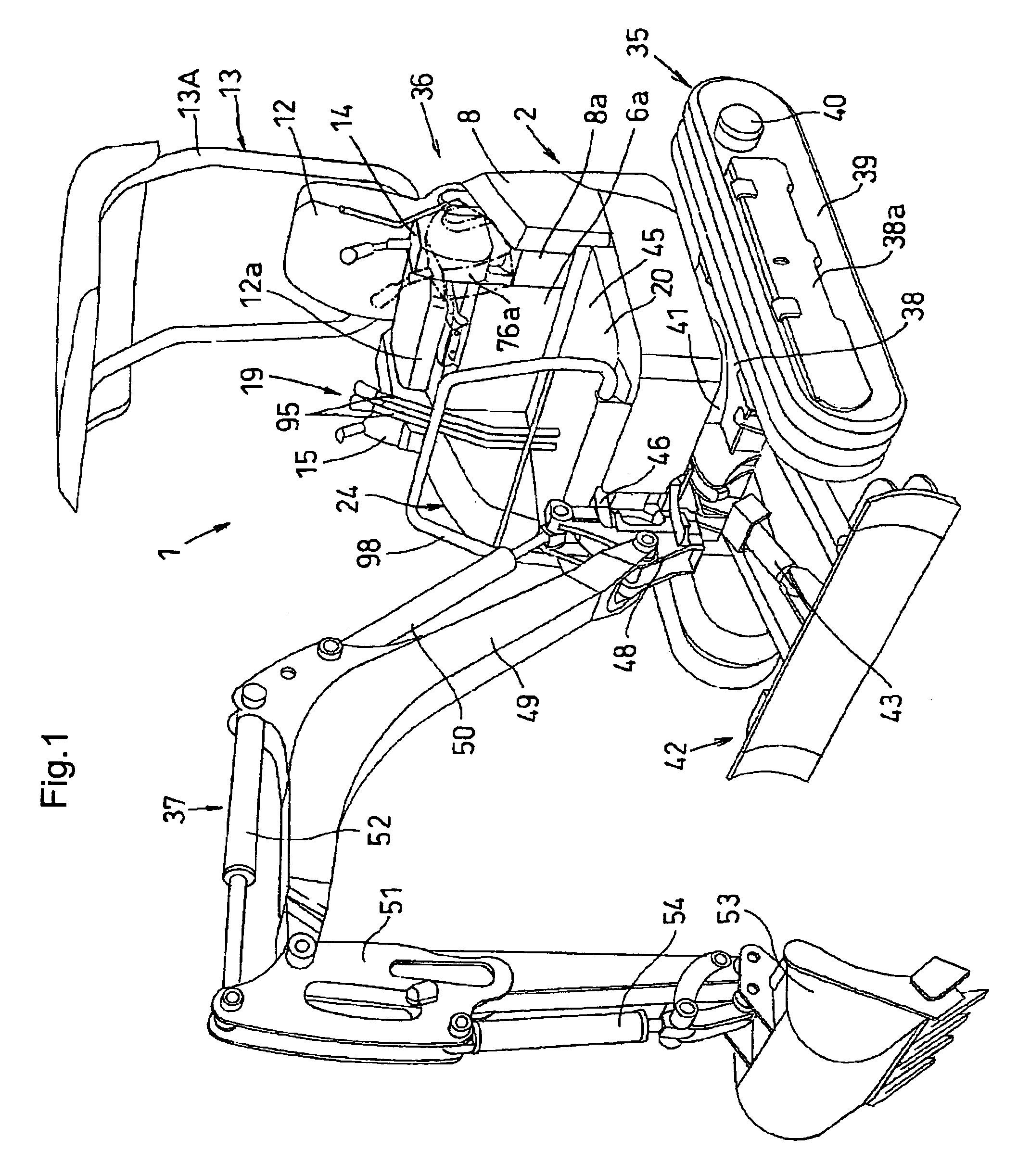
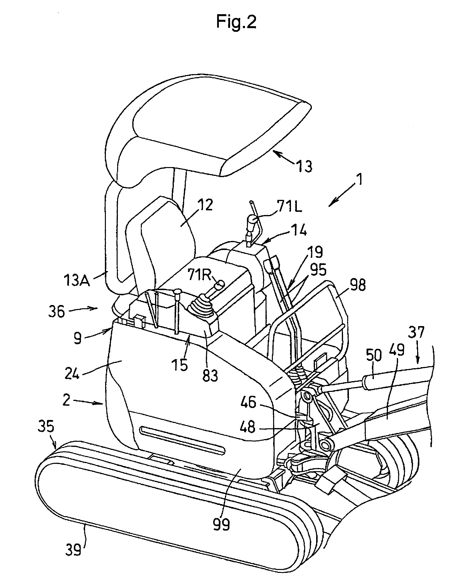
[0047]In FIGS. 1 through 12, numeral 1 denotes a standard or compact rear swiveling type backhoe as an example of the swiveling utility machine relating to the present invention. This backhoe 1 includes, as principal components thereof, a pair of right and left crawler traveling units 35, an upper structure 36 having a swivel deck 2, an excavator 37 mounted on the swivel deck 2, and a dozer 42 disposed forwardly of the crawler traveling units 35.

[0048]The crawler traveling units 35 include track frames 38 having a pair of right and left side frames 38a, each side frame 38a rotatably supporting drive and driven wheels at fore and aft portions and a plurality of free wheels therebetween. A crawler 39 formed of rubber or iron is entrained about these wheels. The drive wheels are driven by traveling drive units such as a pair of right and left hydraulic motors 40...


PUM


Abstract

A swiveling utility machine includes a swivel deck, an engine disposed at a rear portion of the swivel deck, a radiator disposed adjacent the engine, a driver's seat, a right implement controller disposed on the right side of the driver's seat and a left implement controller disposed on the left side of the driver's seat. A support frame is disposed at a rear portion of the swivel deck in such a manner as to create a rectangular space inside the swivel deck, the engine being mounted within the rectangular space. The driver' seat is disposed upwardly of the support frame. The right implement controller is secured to a right side of the support frame, and the left implement controller is attached to a left side of the support frame to be switchable in its posture between an operational posture and a retracted posture. An access step is disposed at a front portion of the support frame, and an access entrance is provided on a left side of the access step.

Description

BACKGROUND OF THE INVENTION[0001]1. Field of the Invention[0002]The present invention relates to a swiveling utility machine having a swivel deck, an engine disposed at a rear portion of the swivel deck, a radiator disposed adjacent the engine, a driver's seat, a right implement controller disposed on the right side of the driver's seat and a left implement controller disposed on the left side of the driver's seat.[0003]2. Description of the Related Art[0004]A conventional swiveling utility machine is known from e.g. Japanese Patent Application “Kokai” No. 11-81378. This machine includes an engine disposed at a rear portion of a swivel deck, a radiator disposed on either right or left side of the engine, and a support frame mounted on the swivel deck to be disposed over and across these, with an air cleaner and a muffler being mounted inside the support frame. In the case of this swiveling utility machine, its support frame is constructed as a three-post type including two front pos...

Claims


Application Information

Patent Timeline
Patent Type & Authority Patents(United States)
IPC IPC(8): B62D33/08E02F9/08E02F9/16
CPCE02F9/0808E02F9/0833E02F9/163E02F9/08
Inventor UEDA, MASAAKIFUJIWARA, JUNICHISUGAHARA, SAKAE
Owner KUBOTA LTD
Why Eureka
Try Eureka