Steam turbine and method for operating same

a steam turbine and steam technology, applied in steam engine plants, machines/engines, non-positive displacement engines, etc., can solve the problems of high load on the outer wall, leakage or cracks in the outer wall, and partial condensation of process steam, etc., to achieve the effect of easy and inexpensive construction

Active Publication Date: 2022-06-07
SIEMENS ENERGY GLOBAL GMBH & CO KG
View PDF27 Cites 0 Cited by
  • Summary
  • Abstract
  • Description
  • Claims
  • Application Information

AI Technical Summary

Benefits of technology

[0028]It may furthermore be advantageous if the intermediate superheater is arranged outside the steam turbine outer housing. This is advantageous in particular with regard to the assembly, disassembly, maintenance and repair of the steam turbine.
[0029]In the case of a steam turbine according to the invention, it is furthermore possible that the high-pressure inner housing and the low-pressure inner housing are provided as separate components. This has the advantage that the steam turbine can be constructed easily and inexpensively in accordance with the modular principle. The present invention relates here advantageously to the expansion of process steam in a single steam turbine outer housing from a high pressure to a pressure below an intermediate superheating pressure. A low-pressure expansion may be performed in a separate portion of the same steam turbine or in a separate low-pressure steam turbine.

Problems solved by technology

In the low-pressure part, the temperature of the process steam falls significantly, which can result in partial condensation of the process steam.
Without such an intermediate superheating process, it would be necessary for the steam turbine to be stopped, because condensing water droplets could strike the rotating turbine blades and would thus cause damage to the turbine.
In the case of the implementation of intermediate superheating systems in steam turbines, the material of the outer wall is subjected to high loading, in particular between the individual turbine stages.
This can lead to leaks or cracks in the outer wall.
There is also the risk that wet steam parameters prevail during extraction of the cold process steam from the first turbine stage, and condensate thus forms on the inner wall of the outer housing.
These additional inflow housings can however lead to energy losses.

Method used


Image

  • Steam turbine and method for operating same

Examples


Embodiment Construction

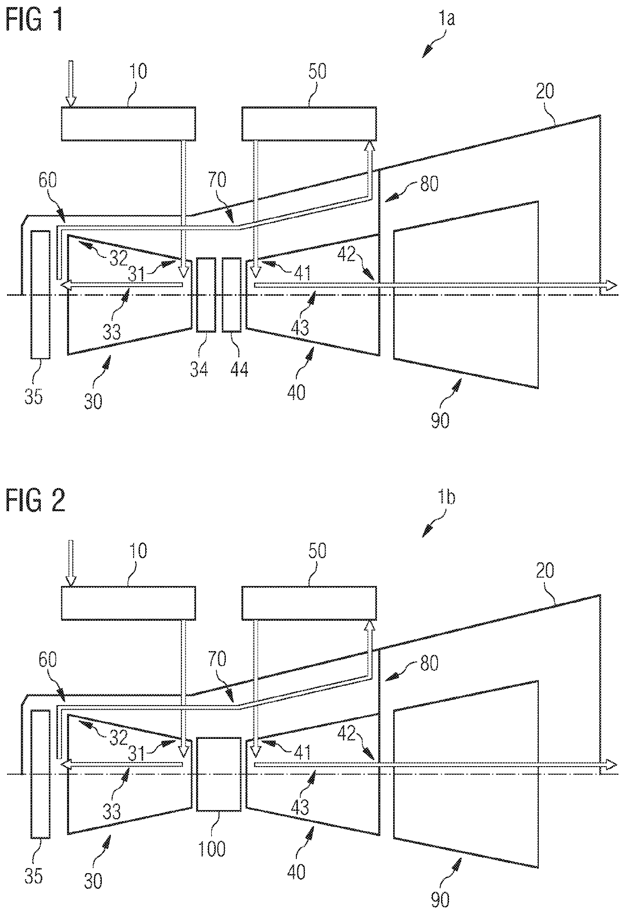
[0036]Elements of identical function and mode of action are denoted in each case by the same reference designations in FIGS. 1 and 2.

[0037]FIG. 1 illustrates a steam turbine 1a according to a first embodiment. The steam turbine 1a has a steam turbine outer housing 20, in which there are situated a high-pressure inner housing 30, a low-pressure inner housing 40 in the form of a medium-pressure inner housing, and a further low-pressure inner housing 90. Arranged upstream of the high-pressure inner housing 30 is a fresh steam or process steam source 10 for the supply of process steam to the high-pressure inner housing 30. The high-pressure inner housing 30 has a first process steam inlet portion 31 and a first process steam outlet portion 32 for conducting process steam through the high-pressure inner housing 30 from the first process steam inlet portion 31 to the first process steam outlet portion 32 in a first process steam expansion direction 33. The low-pressure inner housing 40 ha...


PUM


Abstract

A steam turbine, having a steam turbine outer housing; a high-pressure inner housing having first process steam inlet and outlet sections for conducting process steam therethrough from the inlet to the outlet section in a first process steam expansion direction; a low-pressure inner housing having second process steam inlet and outlet sections for conducting process steam therethrough from the second process steam inlet section to the second process steam outlet section in a second process steam expansion direction; and an intermediate superheater, which is arranged downstream of the high-pressure inner housing and upstream of the low-pressure inner housing, wherein the high-pressure and low-pressure inner housings are arranged within the steam turbine outer housing and the high-pressure and the low-pressure inner housings are arranged in such a way that the first steam inlet section of the high-pressure inner housing faces the second steam inlet section of the low-pressure inner housing.

Description

CROSS REFERENCE TO RELATED APPLICATIONS[0001]This application is the US National Stage of International Application No. PCT / EP2018 / 053634 filed 14 Feb. 2018, and claims the benefit thereof. The International Application claims the benefit of German Application No. DE 10 2017 211 295.6 filed 3 Jul. 2017. All of the applications are incorporated by reference herein in their entirety.FIELD OF INVENTION[0002]The present invention relates to a steam turbine and to a method for operating the steam turbine.BACKGROUND OF INVENTION[0003]In steam power plants, steam is used as working medium for the operation of steam turbines. The water vapor is heated in a steam boiler and flows as process steam via pipelines into the steam turbine. In the steam turbine, the previously absorbed energy of the working medium is converted into kinetic energy. By means of the kinetic energy, a generator is operated, which converts the generated mechanical power into electrical power. The expanded and cooled pro...

Claims


Application Information

Patent Timeline
Patent Type & Authority Patents(United States)
IPC IPC(8): F01K7/22F01D25/26F01D25/12
CPCF01K7/22F01D25/26F01D25/12F05D2220/31F05D2240/14F05D2260/2322F05D2260/941F01D1/04F01K7/025
Inventor LEIDINGER, BERNDPREIBISCH, STEFANRUHSLAND, STEFANIE
Owner SIEMENS ENERGY GLOBAL GMBH & CO KG
Why Eureka
Try Eureka