Collapsible control lever

Inactive Publication Date: 2014-04-15
VINCE WARREN LEVERS
View PDF33 Cites 0 Cited by
  • Summary
  • Abstract
  • Description
  • Claims
  • Application Information

AI Technical Summary

Benefits of technology

[0022](11) provides a low cost, easy to maintain, reliable, relatively simple

Problems solved by technology

Elongate levers used on control systems are susceptible to breakage caused by inadvertent impact.
For example, motorcycles and bicycles are susceptible to spills and falls, particularly when being used in a race or off-road.
The familiar brake and clutch cable control lever assemblies on a motorcycle, which are mounted on the front of the motorcycle handlebars, are particularly vulnerable to impact and fracture during these incidents, even during relatively minor spills and falls.
Similarly, motorcycle drivers themselves can be injured during a spill or fall by impact with these lever assemblies.
A broken brake or clutch lever assembly arising during a spill renders an otherwise functional motorcycle inoperative.
Such an incident can be particularly troublesome during a race, where time lost replacing a broken lever assembly will usually result in losing the race, or during off-road operations, where assistance is usually a great distance away.
Unfortunately, the increased range of motion of these types of levers prevents them from having a clearly defined control motion during

Method used


Image

  • Collapsible control lever
  • Collapsible control lever
  • Collapsible control lever

Examples


Embodiment Construction

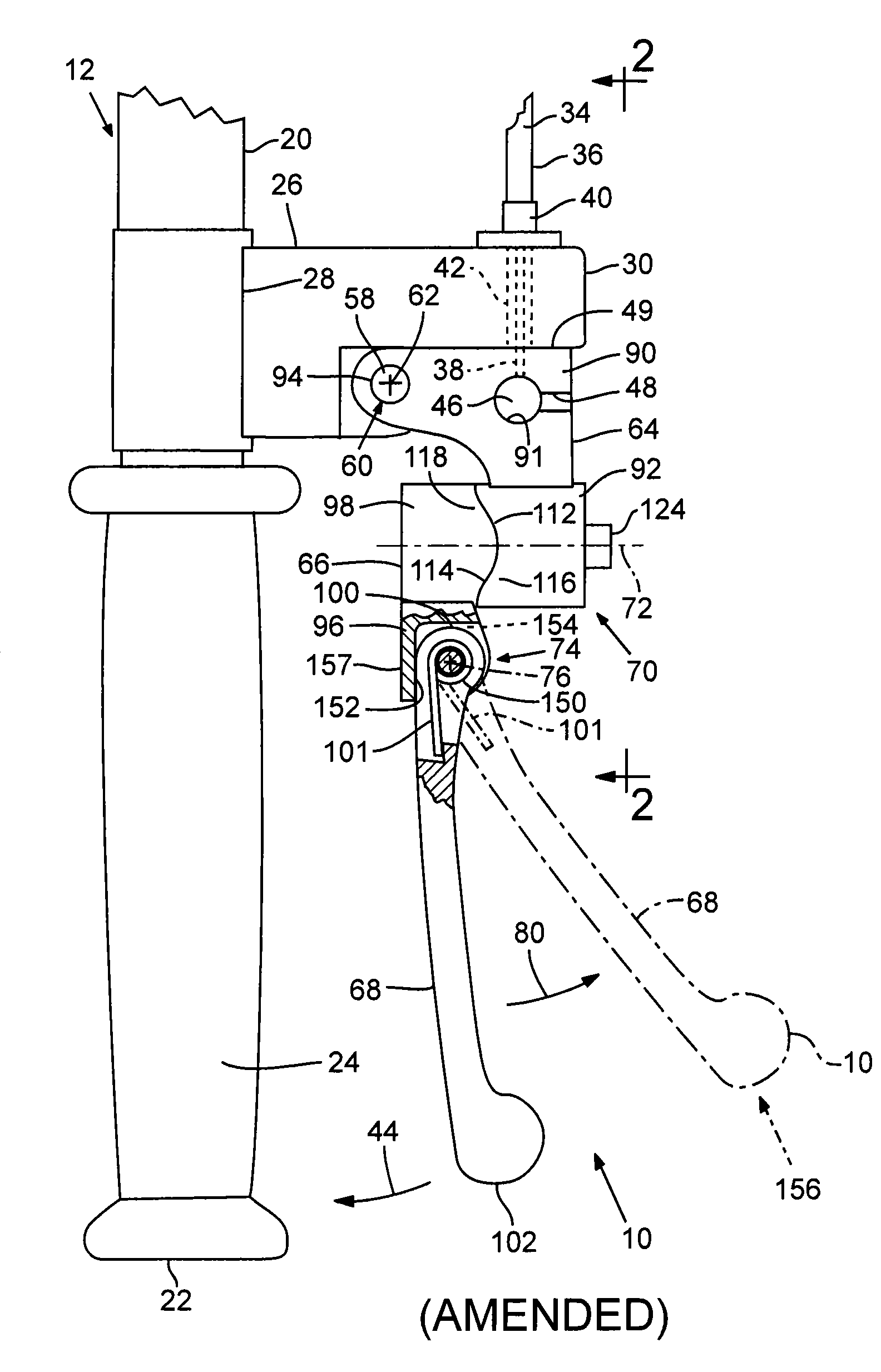
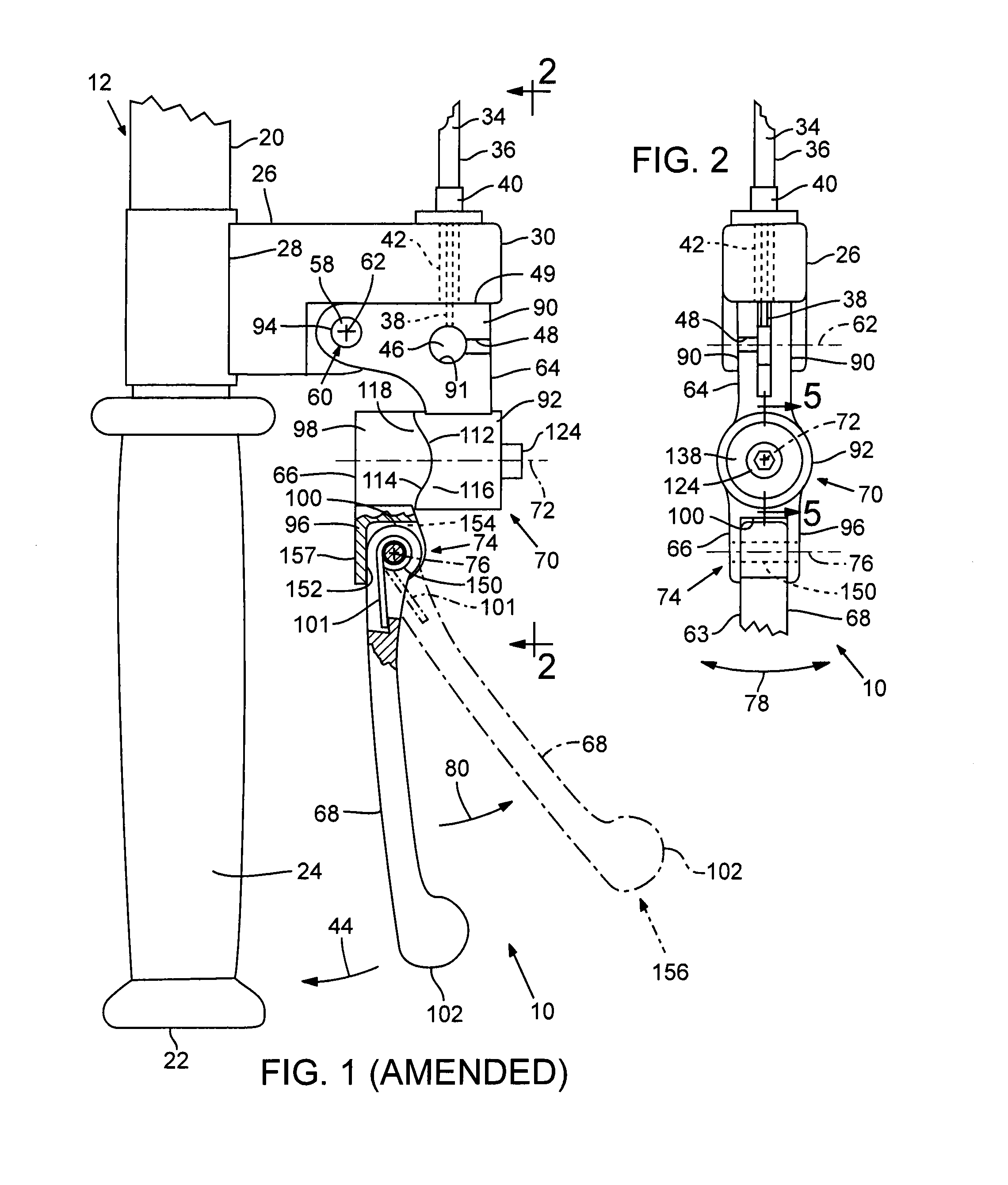
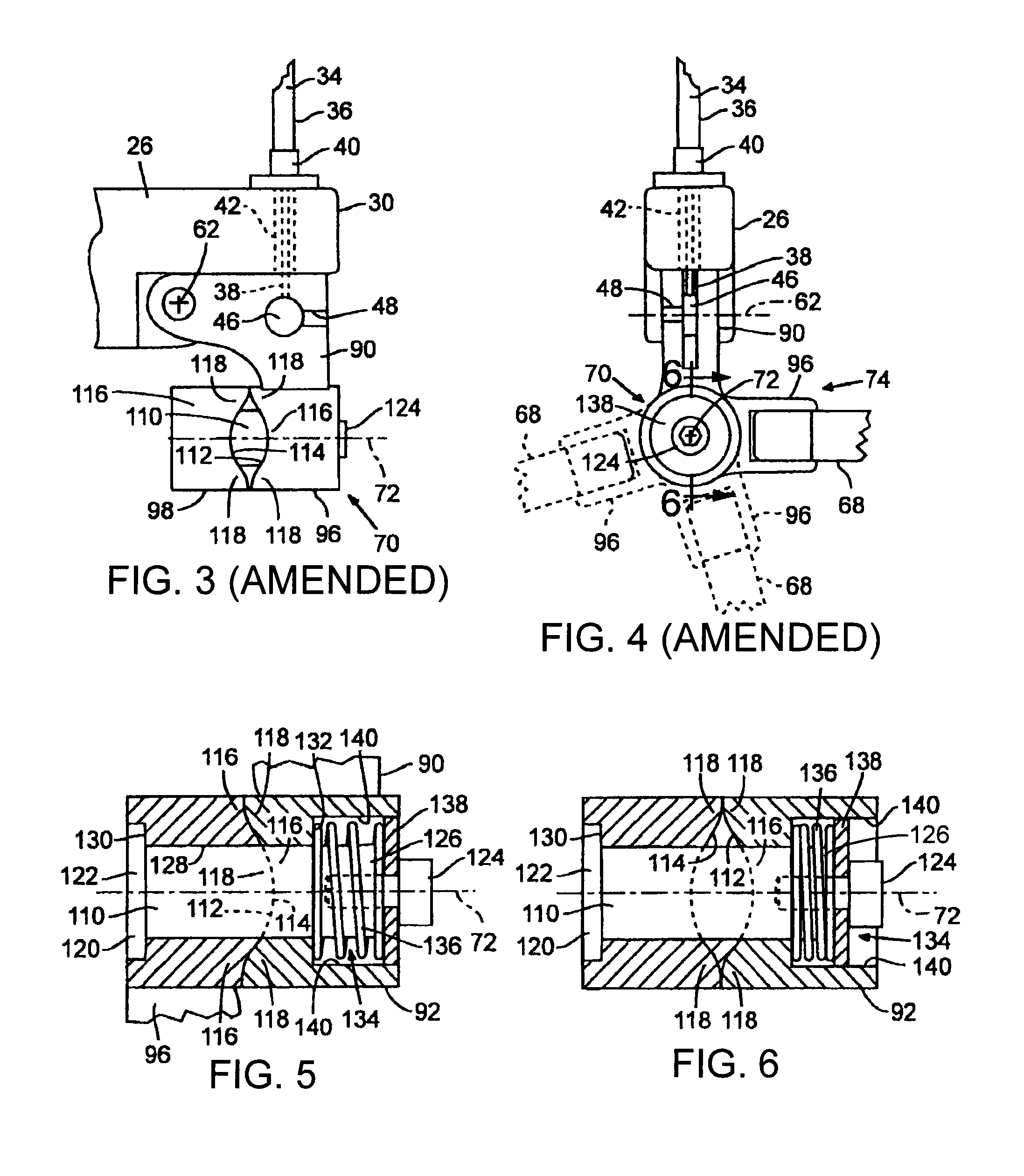
[0032]A collapsible lever 10 constructed accordingly to an embodiment of the invention for use, in the present case, with a cable lever control system 12 is shown in FIGS. 1-6.

[0033]The construction and use of such a cable lever control system 12 is known. Accordingly, to provide a comprehensive disclosure without unduly lengthening the specification, this specification incorporates by reference the disclosures of U.S. Pat. Nos. 4,088,040 to Ross-Myring, 4,726,252 to Dawson, and 4,730,509 to Homady. These references provide greater detail regarding the general construction and use of cable lever control systems.

[0034]In general, as shown in FIG. 1, the cable lever control system 12 includes a handlebar 20 having an end 22 with the cable control system 12 secured near said end. A handle grip 24, usually constructed of a resilient material, is secured to the end portion of the handlebar 20. A pivot mount 26 extends from the handlebar 20 generally perpendicular to and near the handle g...


PUM


Abstract

A collapsible control lever for use with a control system having levers including a conventional cable control lever system such as those found on motorcycles and bicycles. The lever has three independent axes of rotation about which sections of the lever rotate during impact to deflect the impact force. However, the lever remains rigid in the direction of the applied control force when in its operational position during normal operation. The lever restores itself to its operational position following impact with minimal user assistance. The lever may be sized and shaped to be easily retrofit into existing known pivot bases, and at least one of the pivots may include an improved swivel pivot that is sealed from mud and other debris in its operational configuration. The improved swivel pivot has a first and second generally cylindrical frame portion that rotate about a pivot pin with each frame portion having a sliding surface with a smoothly alternating concave and convex-shaped sliding surface. The two surfaces are in intermeshed alignient when the lever is in its operational configuration. The two surfaces slide out of intermeshed alignment during impact. A coil spring received within the frame portions urges the two frame portions toward each other and the misaligned concave and convex surfaces urge the frame portions to rotate to restore the sliding surfaces into intermeshed alignment following an impact.

Description

CONTINUATION REISSUE APPLICATIONS [0001]This application is a broadening reissue of U.S. patent application Ser. No. 08 / 982,130 filed on Dec. 1, 1997 which issued as U.S. Pat. No. 6,047,611 on Apr. 11, 2000, and a parent of continuation-in-part U.S. patent application Ser. No. 13 / 240,414, filed on Sep. 22, 2011 and currently pending. [0002]The present invention relates to a collapsible and recoverable control lever for use with systems having control levers including hand-operated cable control systems such as brake and clutch levers on motorcycles, brake levers on bicycles, other control lever systems, and the like.BACKGROUND OF THE INVENTION[0003]Elongate levers used on control systems are susceptible to breakage caused by inadvertent impact. For example, motorcycles and bicycles are susceptible to spills and falls, particularly when being used in a race or off-road. The familiar brake and clutch cable control lever assemblies on a motorcycle, which are mounted on the front of the...

Claims


Application Information

Patent Timeline
IPC IPC(8): G05G11/00F16C1/10B62K23/06
CPCB62K23/06Y10T74/20287Y10T74/20438
Inventor WARREN, VINCENT M.
Owner VINCE WARREN LEVERS
Why Eureka
Try Eureka