Apparatus for automatically adjusting clearance of support yoke
What is AI technical title?
AI technical title is built by Patsnap AI team. It summarizes the technical point description of the patent document.
a technology of automatic adjustment and support yoke, which is applied in the direction of mechanical equipment, transportation and packaging, and gearing, etc., can solve problems such as vibration generation and nois
Active Publication Date: 2012-09-04
HL MANDO CORP
View PDF12 Cites 15 Cited by
Summary
Abstract
Description
Claims
Application Information
AI Technical Summary
This helps you quickly interpret patents by identifying the three key elements:
Problems solved by technology
Method used
Benefits of technology
Benefits of technology
[0019]Accordingly, the present invention has been made to solve the above-mentioned problems occurring in the prior art, and an object of the present invention is to provide an apparatus for automatically adjusting clearance of a support yoke, the apparatus including: a support yoke, which includes at least one first guide part formed along a circumference thereof while extending from a first large width part to a first small width part and at least one first fixing groove formed at the first large width part; a cam, which includes at least one second guide part formed along a circumference of the cam while extending from a second large width part to a second small width part and at least one second fixing groove formed at the second large width part; at least one spacing member, which is disposed along the second guide part and has a portion protruding from the second guide part; and at least one elastic member disposed between the first fixing groove and the second fixing groove, so that in a case where the support yoke is worn away due to friction, etc. against a rack bar, when the cam performs relative rotation movement respective to the support yoke by means of an elastic force of the elastic member disposed between the first fixing groove of the support yoke and the second fixing groove of the cam, the spacing member pushes the support yoke in a direction of the rack bar while moving along the first guide part of the support yoke so as to maintain a predetermined interval between the spacing member and the support yoke, thereby maintaining clearance of the support yoke at a predetermined degree.
Problems solved by technology
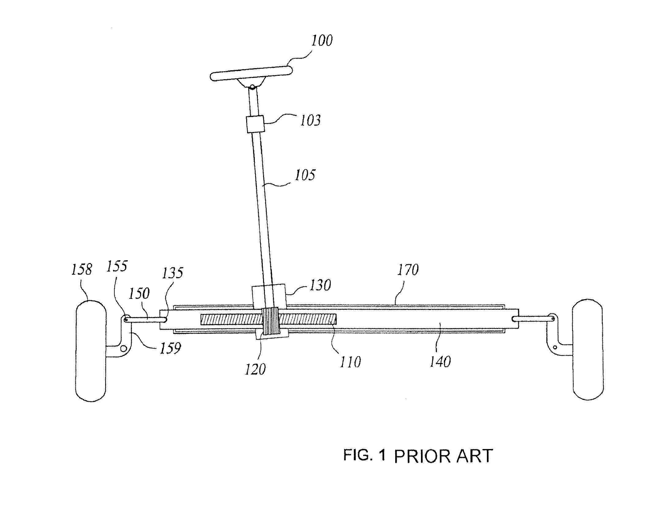
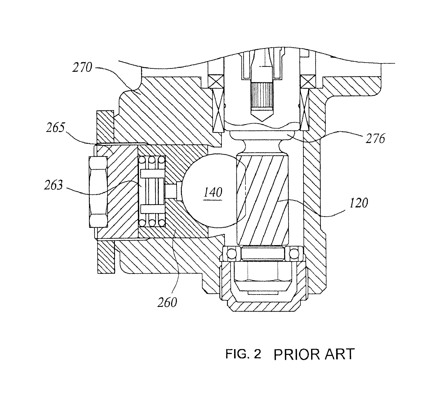
As a result, the yoke plug and the support yoke collide with each other, thereby generating noise due to vibration.
Method used
Image
Click on the blue label to locate the original text in one second.
Reading with bidirectional positioning of images and text.
Examples
first embodiment
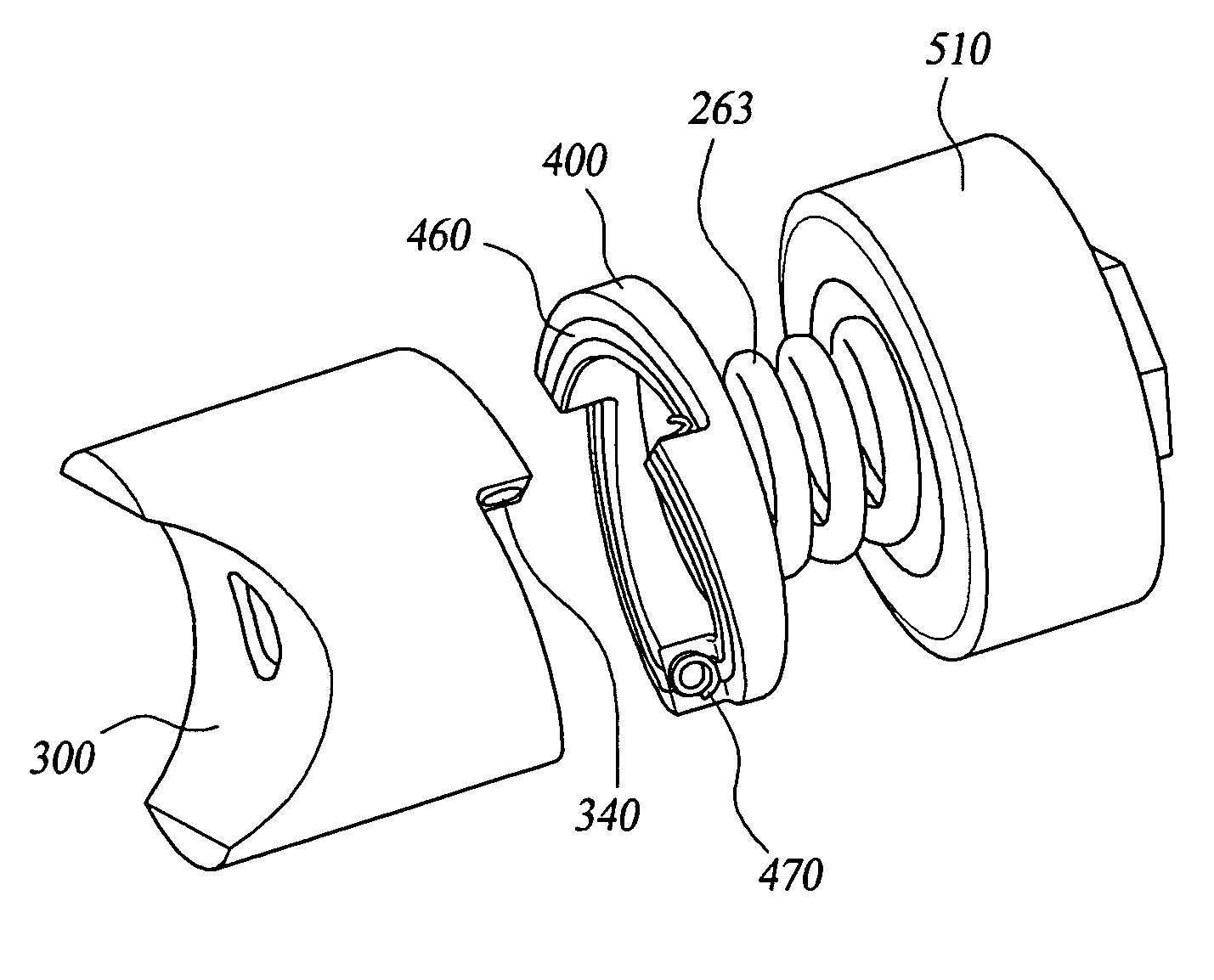
[0040]As shown in FIGS. 3a, 3b, and 3c, a support yoke 300 according to the present invention includes at least one first guide part 330 formed along a circumference thereof while extending from a first large width part 310 to a first small width part 320 and at least one first fixing groove 340 formed at the first large width part 310.
[0041]Herein, the first large width part 310 is a part where the first fixing groove 340 is formed. Also, if an imaginary line extends from the first large width part 310 shown in FIG. 3a, the first small width part 320 is a part formed between the imaginary line positioned just before a point, at which another large width part begins, and the first guide part 330.
[0042]At least one first guide part 330 is formed at one end of the support yoke 300 along a circumference thereof, and extends from the first large width part 310 to the first small width part 320, while having an elongated shape.
[0043]In the first embodiment of the present invention, it is...
second embodiment
[0083]FIG. 6a is a sectional view of the apparatus for automatically adjusting the clearance of a support yoke according to the present invention; and FIG. 6b is view illustrating an enlarged part A of FIG. 6a.
[0084]As shown in FIGS. 6a and 6b, an apparatus for automatically adjusting clearance of a support yoke according to a second embodiment of the present invention includes a support yoke 610, a yoke spring 263, a first cam 630, a spacing member 640, a second cam 650, a yoke plug 660, and an elastic member 670.
[0085]The yoke plug 660 has a shape equal to a shape of a conventional yoke plug and is made from material equal to the conventional yoke plug. Meanwhile, the support yoke 610 yoke plug 660 has a fixing hole 615, with which the spacing member 640 is assembled.
[0086]The yoke spring 263 is inserted into a rear surface opposite to a surface making contact with the rack bar 140, the first cam 630 is assembled, and then the spacing member 640 is assembled with the fixing hole ...
PUM
Abstract
Disclosed is an apparatus for automatically adjusting clearance of a support yoke of a rack and pinion type steering apparatus, the apparatus including: a support yoke making contact with one side of a rack bar so as to support the rack bar; at least one cam assembled with one side of the support yoke so as to support the support yoke; a yoke plug which is positioned at one side of the cam so as to support the cam and is assembled with a rack housing; and a yoke spring included at one side of the support yoke so as to apply elastic force to the support yoke in a direction of the rack bar. In a case where the support yoke is worn away due to friction, etc. against the rack bar, while the cam performs relative rotation movement respective to the support yoke by means of an elastic force of the elastic member disposed between the support yoke and the cam, the spacing member pushes the support yoke in a direction of the rack bar so as to maintain a predetermined interval between the spacing member and the support yoke, thereby maintaining clearance of the support yoke in a predetermined degree.
Description
CROSS-REFERENCE TO RELATED APPLICATION[0001]This non-provisional application claims priority under 35 U.S.C §119(a) on Patent Application No. 10-2007-0053280 filed in Korea on MAY 31, 2007, the entire contents of which are hereby incorporated by reference.BACKGROUND OF THE INVENTION[0002]1. Field of the Invention[0003]The present invention relates to an apparatus for automatically adjusting the clearance of a support yoke, and more particularly to an apparatus for automatically adjusting clearance of a support yoke, in which a cam, a spacing member, and an elastic member are included, and in a case where a support yoke is worn away due to friction, etc. against a rack bar, while the cam performs relative rotation movement respective to the support yoke by means of an elastic force of the elastic member disposed between the support yoke and the cam, the spacing member pushes the support yoke in a direction of the rack bar so as to maintain a predetermined interval between the spacing...
Claims
Application Information
Patent Timeline
Application Date:The date an application was filed.
Publication Date:The date a patent or application was officially published.
First Publication Date:The earliest publication date of a patent with the same application number.
Issue Date:Publication date of the patent grant document.
PCT Entry Date:The Entry date of PCT National Phase.
Estimated Expiry Date:The statutory expiry date of a patent right according to the Patent Law, and it is the longest term of protection that the patent right can achieve without the termination of the patent right due to other reasons(Term extension factor has been taken into account ).
Invalid Date:Actual expiry date is based on effective date or publication date of legal transaction data of invalid patent.

