Indexable drill

a drill bit and indexing technology, applied in the direction of twist drills, cutting inserts, manufacturing tools, etc., can solve the problems of reducing the transmission clamping force, affecting the adherence between the two faces, and posing repetitive machining, etc., to achieve high degree of attachment rigidity and attachment accuracy, reliable transmission torque, and large clamping force

Inactive Publication Date: 2012-01-10
MITSUBISHI MATERIALS CORP
View PDF22 Cites 9 Cited by
  • Summary
  • Abstract
  • Description
  • Claims
  • Application Information

AI Technical Summary

Benefits of technology

[0022]According to the indexable drill of the present invention, the crosshatch angles of the clamp receiving faces and torque receiving faces of the cutting insert are formed smaller within a range of 2° or less than the crosshatch angles of the clamp faces and torque transmission faces of the drill body, with the result that when the cutting insert is mounted in the recessed part of the drill body, it is possible to obtain the strong adhesion of the torque transmission faces and torque receiving faces and to reliably transmit torque from the drill body to the cutting insert in comparison to the case where the mutual crosshatch angles are equal. Moreover, as the cutting insert is clamped and held so that the drill body elastically deforms and the clearances of the clamp faces and clamp receiving faces are gradually filled, it is possible to exert a large clamping force on the cutting insert, and to firmly integrate the cutting insert and drill body.
[0023]Moreover, when the cutting insert is mounted in the recessed part of the drill body, as the cutting insert is guided so that the clearances are filled due to the slight variance in the mutual crosshatch angles, it is possible to have the axis of the cutting insert and the axis of the drill body coincide, and to firmly hold the cutting insert in this state. Accordingly, it is possible to maintain a high degree of attachment rigidity and attachment accuracy, and to enhance the precision of machined holes.
[0024]Furthermore, as the first female screw part and second female screw part formed inside the insertion hole are made as reverse screws, even when the clamping screw which is screwed into the first female screw part contacts the screw part which is screwed into the second female screw part, it is possible to prevent the screw part from being driven and loosened by the rotation of the clamping screw, and to reliably enlarge the interstice of the slit, thereby enabling the cutting insert to be suitably attached to and removed from the recessed part of the drill body.
[0025]In addition, by filling at least part of the slit with resin, it is possible to prevent the ingestion of chip into the slit during cutting, and to prevent the infliction of flaws and the like on the inner surface of the workpiece. Furthermore, by filling the slit with resin, it is possible to prevent a resonance phenomenon during cutting, and to reduce cutting noise.
[0026]Furthermore, as the margins of the cutting insert form the taper angle of a second tapered part larger than that of a first tapered part, it is possible to maintain the clearance of the margin and the machined hole, to reduce cutting resistance and interference during withdrawal, and to stably conduct cutting.

Problems solved by technology

With this indexable drill, it has only been possible to conduct repetitive machining by replacing the cutting inserts provided with cutting edges, which become worn by the cutting of workpieces.
However, with the aforementioned indexable drill, as the crosshatch angles of the clamp receiving faces and torque receiving faces of the cutting insert are identical to the crosshatch angles of the clamp faces and torque transmission faces of the drill body, the problem arises that if these faces are not formed with a high degree of accuracy, it may happen that adherence between these faces is impaired, that the transmitted clamping force is reduced, and that attachment rigidity of the cutting inserts in the drill body cannot be fully maintained.
Furthermore, in such cases, there is the problem that the mutual axes of the drill body and cutting insert may be deviated during attachment of the cutting insert.
Accordingly, when such problems occur, they result in impairment of the accuracy of machined holes.
Consequently, when the clamping screw is loosened whereby the head of the clamping screw is made to contact the screw part in order to enlarge the interstice of the slit, there is the problem that the screw part is driven by the rotation of the clamping screw.
In such cases, there is the problem that it may happen that the screw part is removed from the insertion hole, that the interstice of the slit cannot be enlarged, and that the cutting insert cannot be suitably attached and removed.
Furthermore, as the slit is open in the state where the cutting insert is integrated with the drill body, there is the problem that a resonance phenomenon occurs inside the space formed by the slit during cutting, and that a very loud cutting noise occurs.
It may also happen that chip is ingested by the slit, damaging the inner face of the machined hole.
In addition, with the aforementioned indexable drill, when, for example, stainless steel material or the like is subjected to cutting, it may happen that a strong tightening force is imposed on the drill from the machined hole, and that cutting resistance becomes large, impeding the conduct of stable cutting.
Furthermore, even when the drill body is withdrawn after formation of the machined hole, there is the problem that interference with the machined hole may occur, rendering it impossible to suitably withdraw the drill.

Method used


Image

  • Indexable drill
  • Indexable drill
  • Indexable drill

Examples


Embodiment Construction

[0036]Below, the indexable drill pertaining to a first embodiment of the present invention is described with reference to FIG. 1 to FIG. 9.

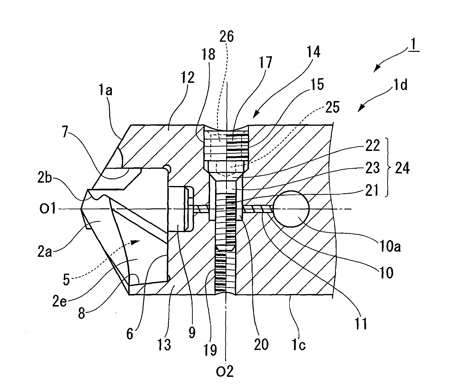
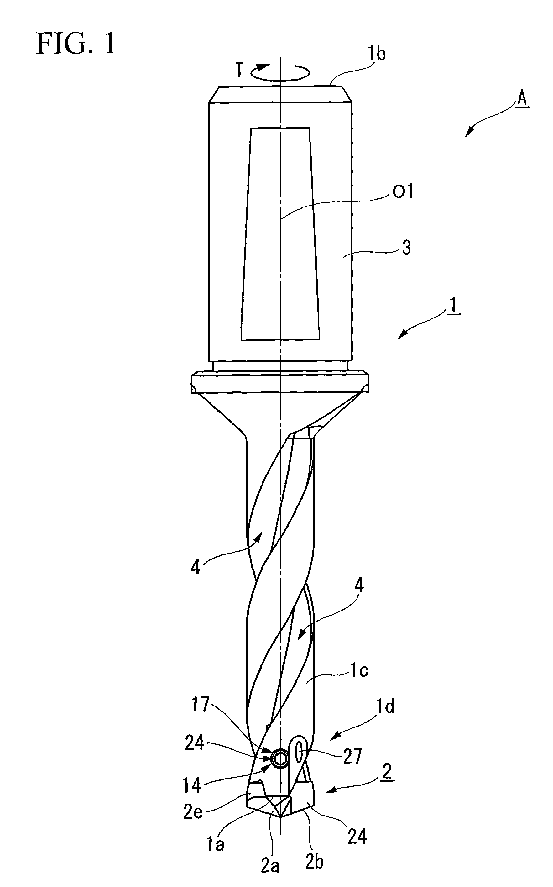
[0037]As shown in FIG. 1, an indexable drill A pertaining to an embodiment of the present invention is composed of a drill body 1 which rotates around axis O1 (drill rotation direction T) and which is formed in an approximately cylindrical rod shape, and a cutting insert 2 which has cutting edges 2b on a tip face 2a, and which is removably mounted onto the tip 1a side of the drill body 1.

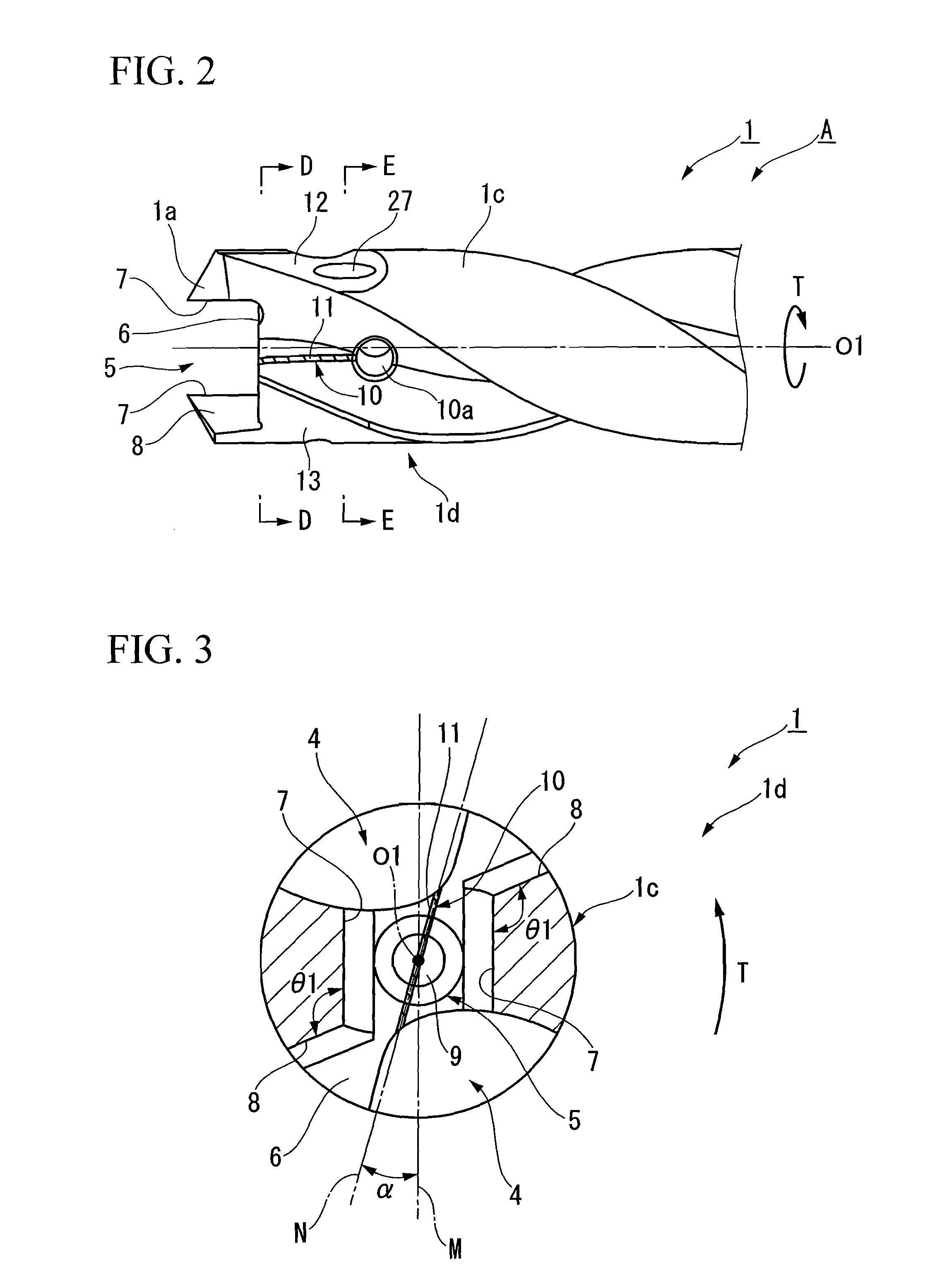
[0038]The drill body 1 is provided with a shank 3 at its proximal end 1b side which is, for example, held by a chuck or the like of a machine tool, and its tip 1a side is formed into an approximately multistage cylinder shape with a contracted diameter relative to this shank 3. At the periphery of the tip 1a side of the drill body 1, a pair of chip discharge flutes 4 which open at tip face 1a are helically formed on mutually opposite sides with axis O1 in between...


PUM

PropertyMeasurementUnit
crosshatch anglesaaaaaaaaaa
angleaaaaaaaaaa

Abstract

An indexable drill is offered which enables suitable integration of a drill body and cutting insert. The crosshatch angles of clamp receiving faces of a cutting insert which are respectively pressed by clamp faces and of torque receiving faces which cross the clamp receiving faces and are adjacent thereto and to which is transmitted the rotary force of the drill body from the torque transmission faces are formed smaller within a range of 2° or less which is less than the crosshatch angles of clamp faces which clamp and hold the cutting insert of the drill body and torque transmission faces which cross these clamp faces and are adjacent thereto and which transmit the rotary force of the drill body to the cutting insert.

Description

CROSS REFERENCE TO RELATED APPLICATIONS[0001]This is a U.S. national phase application under 35 U.S.C. §371 of International Patent Application No. PCT / JP2006 / 307007, filed Mar. 28, 2006 and claims the benefit of Japanese Application 2005-094310, filed Mar. 29, 2005. The International Application was published in Japanese on Oct. 5, 2006 as International Publication No. WO 2006 / 104239 under PCT Article 21(2) the contents of which are incorporated herein in their entirety.TECHNICAL FIELD[0002]The present invention relates to an indexable drill which removably attaches a cutting insert that has cutting edges at its tip on the distal side of the drill body.BACKGROUND ART[0003]Heretofore, as a cutting tool used in perforation machining of workpieces, what is referred to as an indexable drill has been used, which removably attaches a cutting insert having cutting edges at its tip on the distal side of the drill body. With this indexable drill, it has only been possible to conduct repetit...

Claims


Application Information

Patent Timeline
Patent Type & Authority Patents(United States)
IPC IPC(8): B23B51/02
CPCB23B51/02B23B51/0493B23B2205/02B23B2251/02Y10T408/9098Y10T408/9097Y10T408/90993Y10T408/906B23B2251/50B23B51/00
Inventor TANAKA, SHOGO
Owner MITSUBISHI MATERIALS CORP
Why Eureka
Try Eureka