Assembly for fastening a fitting to a manifold

a technology for fittings and manifolds, which is applied in the direction of manufacturing tools, metal working apparatus, light and heating apparatus, etc., can solve the problems of increasing the amount of manifold space left to provide fittings, affecting the quality of the fittings, so as to reduce the risk of tilting or drooping and increase the process control

Active Publication Date: 2012-08-09
MAHLE INT GMBH
View PDF12 Cites 9 Cited by
  • Summary
  • Abstract
  • Description
  • Claims
  • Application Information

AI Technical Summary

Benefits of technology

[0006]The invention provides an assembly for fastening a fitting to a hole in a manifold that receives refrigerant tubes that extend into the manifold transverse the hole in the manifold. The assembly includes a fitting that extends along an axis and presents a pair of slots spaced from one another. In addition, the fitting has a lower section that defines an opening to provide clearance for the refrigerant tubes extending into the manifold. The assembly further includes a bracket that presents a pair of legs that extend in spaced relationship with one another. The legs engage the slots of the fitting to limit rotary movement of the fitting about the axis relative to the bracket before and during brazing of the fitting to the manifold for maintaining clearance between the lower section of the fitting and the refrigerant tubes.
[0008]Thus several advantages of one or more aspects of the invention are the elimination of a tack weld prior to furnace brazing, a compact design due to the fact that the fitting extends in a transverse direction to the refrigerant tubes, the reduction of the risk of tilting or drooping of the fitting during furnace brazing, error proofing due to the ease of assembly of the fitting and bracket, and increased process control due to the fact that the lower part of the fitting can be common regardless of connection requirements, allowing the use of only one sized manifold hole, bracket and braze ring.

Problems solved by technology

However, this type of connection can be undesirable because it adds significantly to the overall length of the heat exchanger.
The problem with attaching fittings in a transverse direction to the refrigerant tubes is the close proximity of the refrigerant tubes to the side of the manifold and the amount of manifold space left to provide the fitting.
However, welding requires a great skill set, can be expensive due to time and labor costs, and leaves the fitting at risk of tilting or drooping during the brazing process which is especially undesirable due to the limited amount of space in the manifold.

Method used


Image

  • Assembly for fastening a fitting to a manifold
  • Assembly for fastening a fitting to a manifold
  • Assembly for fastening a fitting to a manifold

Examples


Embodiment Construction

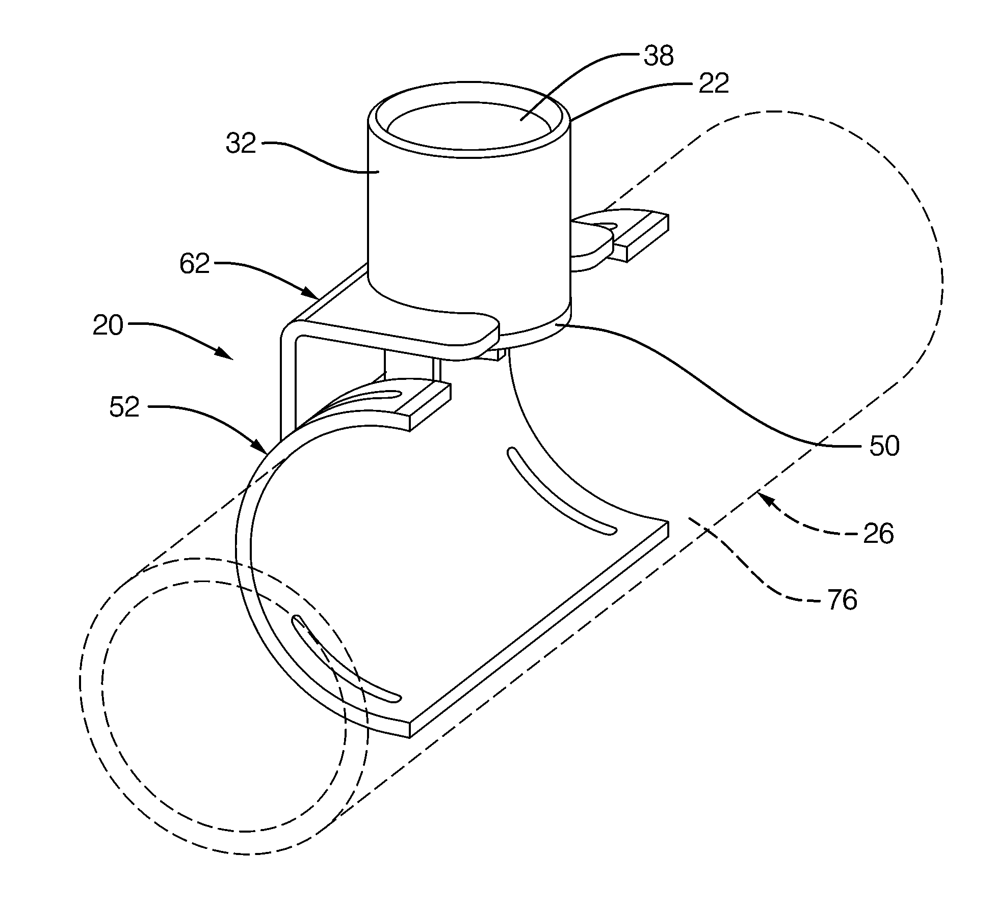
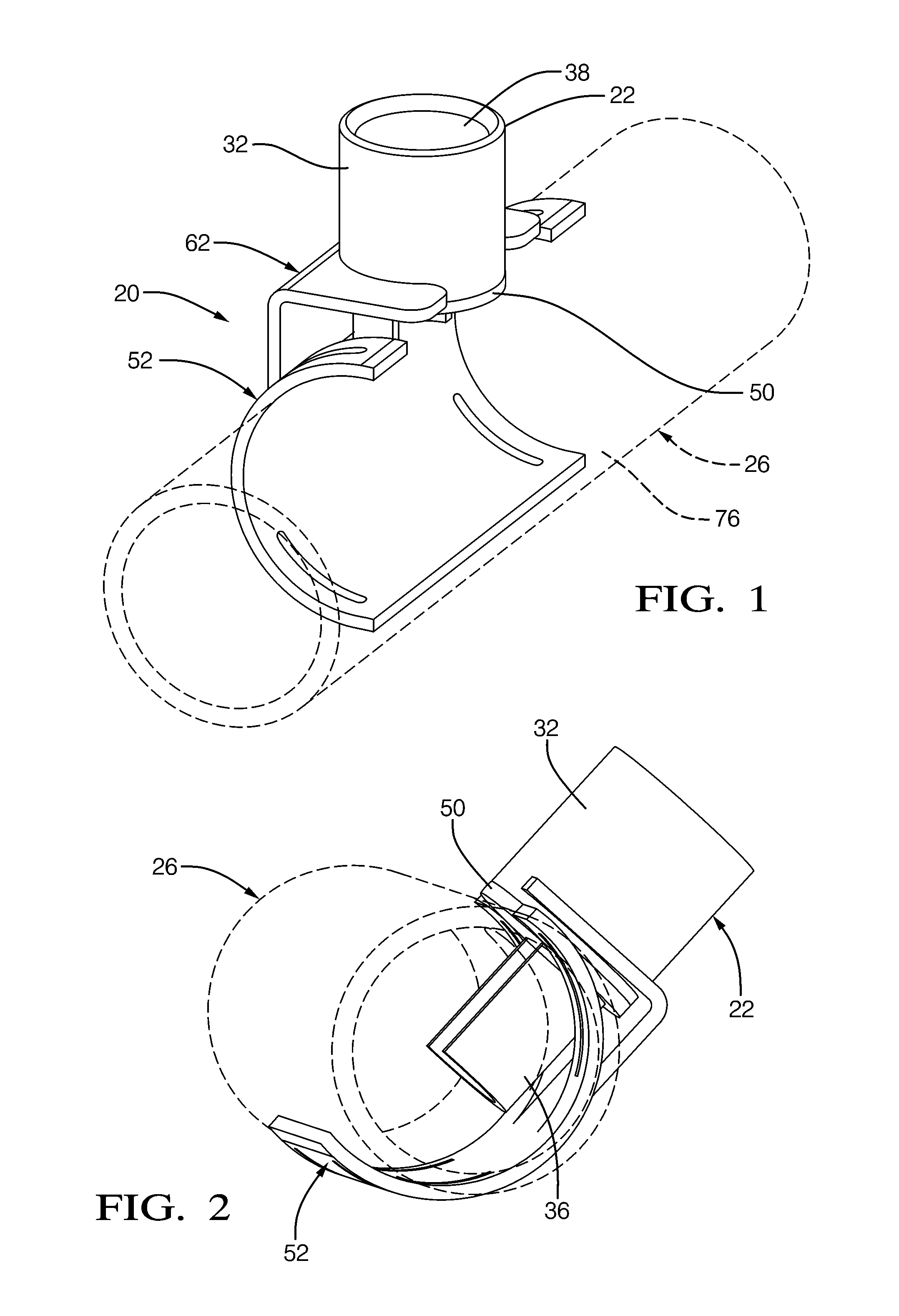
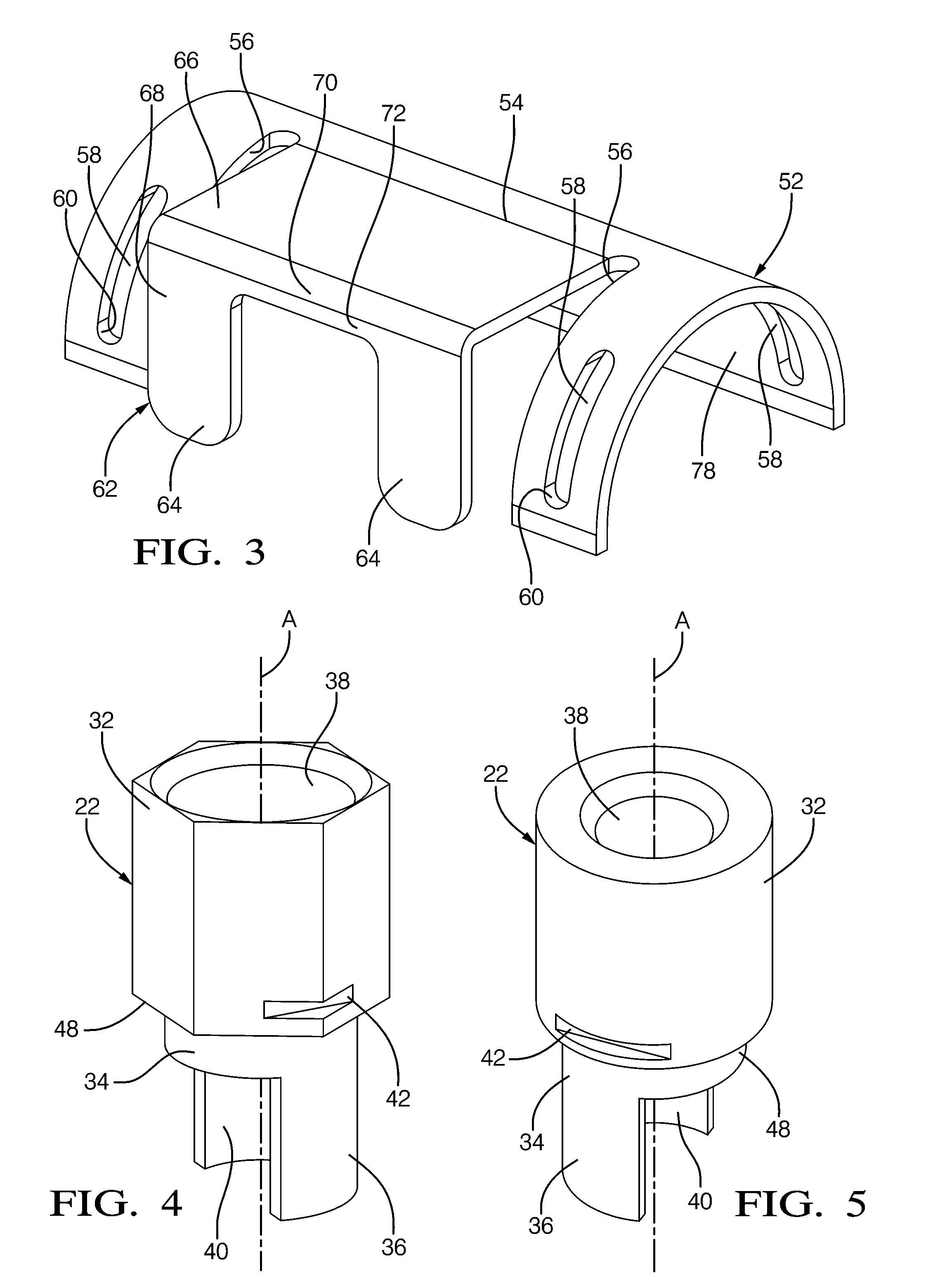
[0019]Referring to the Figures, wherein like numerals indicate corresponding parts throughout the several views, an assembly 20, 120 for fastening a fitting 22, 122 to a hole in a manifold 26, 126 having a tubular shape and receiving refrigerant tubes 28 extending into the manifold 26, 126 transverse the hole in the manifold 26, 126 is generally shown.

[0020]The assembly 20, 120 includes a fitting 22, 122 extending along an axis A. The fitting 22, 122 has an upper section 32, 132, an intermediate section 34, 134 and a lower section 36, 136. A passage 38, 138 for conveying a fluid extends along the axis A through the upper 32, 132, intermediate 34, 134 and lower sections 36, 136. The lower section 36, 136 has a semi-cylindrical shape that defines an opening 40, 140 into the passage 38, 138. The opening 40, 140 provides clearance for the refrigerant tubes 28 extending into the manifold 26, 126, ensuring adequate flow of fluid through the manifold 26, 126, refrigerant tubes 28 and fitti...


PUM

PropertyMeasurementUnit
semi-cylindrical shapeaaaaaaaaaa
cylindrical shapeaaaaaaaaaa
thicknessaaaaaaaaaa

Abstract

An assembly for fastening a fitting to a hole in a tubular manifold having a hole. A plurality of refrigerant tubes extend into the manifold transversely to the hole. The assembly includes a fitting that extends along an axis and defines an opening to provide clearance for the refrigerant tubes extending into the manifold. The fitting also presents a pair of slots in spaced and parallel relationship with one another. The assembly further includes a semi-cylindrical shaped mounting plate including a bracket. The bracket presents a pair of legs which extend in spaced and parallel relationship with one another and engage the slots of the fitting to limit rotary movement of the fitting about the axis relative to the bracket before and during brazing of the fitting to the manifold to maintain a clearance between the lower section of the fitting and the refrigerant tubes.

Description

BACKGROUND OF THE INVENTION[0001]1. Field of the Invention[0002]The subject invention relates to an assembly for fastening a fitting to a hole in a manifold.[0003]2. Description of Related Art[0004]Heat exchangers with manifolds and a fitting secured thereto are widely used in commercial, residential and vehicle applications. Generally, the fitting is oriented in the same direction as the refrigerant tubes where space is the greatest, as shown by U.S. Pat. No. 7,213,640 issued to Fuller et al. on May 8, 2007. However, this type of connection can be undesirable because it adds significantly to the overall length of the heat exchanger. Therefore, it is desirable to attach the fitting in a transverse direction to the refrigerant tubes. The problem with attaching fittings in a transverse direction to the refrigerant tubes is the close proximity of the refrigerant tubes to the side of the manifold and the amount of manifold space left to provide the fitting. Furnace brazing is a desirabl...

Claims


Application Information

Patent Timeline
Patent Type & Authority Applications(United States)
IPC IPC(8): F28F9/007B23P19/00
CPCY10T29/49947F28F9/0251
Inventor DITTLY, BRUCE W.CZACH, JOSEPH B.GAWVE, WARREN L.HAMBRUCH, JOEL T.SNYDER, KEVIN M.
Owner MAHLE INT GMBH
Why Eureka
Try Eureka